Reference original document date : Dec. 5, 2012. This document is translated the original Japanese document Mr. Honda made.
About peff.exe of polygon editor for FMS
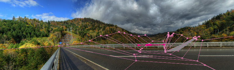
"peff" is named from first character of Polygon Editor For FMS. This is for adding polygon to photo scenery for FMS.
By being able to map image on polygon, aircraft behind of polygon (ex.: bridge, tree) is hidden.
User interface is similar to metasequoia which is 3D modeler, because FMS users use metasequoia for making aircraft model, and I use only metasequoia.
I got permission from author of metasequoia, and thank them here.
Usage of peff.exe - Basic
SimScene.exe
6 faces image which is made by SimScene.exe or other software is needed to edit. It is possible to edit and save without reading 6 faces image, but it isn't possible to putput .scn file.
Basically this is for adding and editing polygon after reading .scn file which is made by SimScene.exe.
_vista.bmp
_vista.bmp is output when SimScene.exe output 6 faces image and .scn. And the .scn has sentence about _vista.bmp.
.scn which is output by peff.exe needs _vista.bmp. When only 6 faces image which are made by Pano2Cube or other software is read by peff.exe and .scn is output by peff.exe, error occurs when .scn is read by FMS, because there is no _vista.bmp.
Above specification has been revised from ver 1.01, because it is boter. From peff.exe ver 1.01, bitmap file name is fixed to fms_vista.bmp, if it doesn't exist in .scn outpu folder, fms_vista.bmp is created by peff.exe.
SimScene.exe has same specification from ver. 1.80.
Available polygon type is limited to square, becaus FMS can't handle triangle.
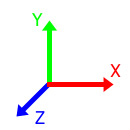
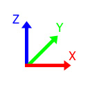
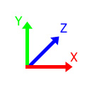
Coordination system
This means as it is called right hand sysytem, left hand sysytem. (ex.: thumb=X axis, forefinger=Y axis, middle finger=Z axis)
|
|
|
| Right hand system (Metasequoia) | Right hand system ? (FMS, blender) | Left hand system (peff DirectX) |
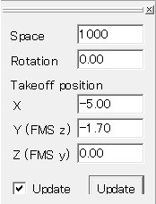
peff has left hand system because DirectX system is adopted. FMS has right hand system ?, but relation with peff is only to exchange Y and z. Plus Z direction of peff is plus Y direction of FMS, aircraft direction. Y, Z of FMS parameter are reflected by this method.
About output file
peff.exe output 3 kind of file.
-
.scn file
It's read by FMS. It has polygon data which is edited by peff.exe. FMS parameter is written in first portion of file as comment, and peff.exe reads it.
-
.pfo file
It's binary file of polygon data. It can't be opened by text editor. It has also 3D cursor position than polygon data.
-
.txt file
Simple editor is appeared by select menu [Show]-[Memo]. You can write smple memo. This memo is saved as text file.
View
From origin and top
Camera (View point) of peff has 2 modes.
"Origin" mode
Camera is at origin of 3D space in "origin" mode, direction of camera can be moved freely. This is same situation as following aircraft in FMS. { Polygon and image are fit each other in this mode. }
" Free" mode
Camera is moved freely in 3D space in "free" mode, but view point is fixed at origin. {?} View point is same as editing by metasequoia. { Polygon and image aren't fit each other in this mode. }
Change camera mode by toolbar
![]()
Toolbar has buttons to set camera mode. "Origin","Free","Top" button are placed from left side. "Top" is part of "free" mode for many opportunity to see from above. When camera mode is changed by these button, camera position and zoom magnification is memorized in the button.
Change camera mode by menu
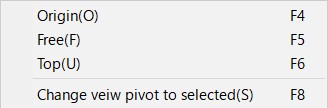
This menu is to set camera position (view point). When this menu is clicked, information which is memorized in button is cleared.
When polygon is selected, "Change view pivot to selected" moves view point to last selected polygon's position. And camera mode is changed in free mode forcibly. It is useful to edit complicated portion.
Change camera direction or position by mouse
- View direction or camera position is rotated by press-and-holding right button of mouse and dragging. When pushing ctrl key, rotation angle step becomes 1/10.
- When press-and-holding middle button of mouse and dragging, camera posision is shifted.
- Mouse wheel rotation changes zoom magnification.
Left button of mouse is used by selection and editing.
Other tool buttons
![]()
These buttons change display of elements which are used in editing.
"Image", "Guide","Polygon" buttons are used to click all group of button.
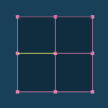
Making polygon
![]()
To click above button in tool panel opens dialog box for making polygon.
If above button isn't found, click [Panel]-[Tool] in menu bar.
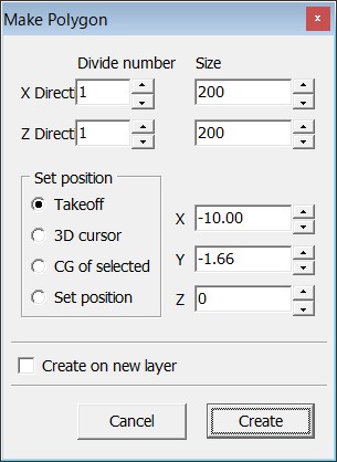
Maximum divide number is 10. Maximum size is double space.
Followings is about setting position.
-
"Aircraft"

Polygon is created at aircraft position which is set by FMS parameter. Position is white (default color) mark which display is turned on and off by clicking above button.
-
"3D cursor"

Polygon is created at 3D cursor position which is red (default color) mark which display is turned on and off by clicking above button.
3D cursol is moved by cursor key, PageUp, PageDown key, numeric keypad. Moving speed is accerarated by space key, decelerated by ctrl key. 3D cursor coordinate is shown at left bottom area in numeral for reference.
"Aircraft position", "3D cursor" mark size are set "4m", "3m" as default. These size can be changed from [File]-[Setting] menu.
Maximum 20 of 3D cursor position can be memorized by [3D cursor]-[Memorize] menu. Memorized position is saved to .pfo file.
- When "CG of selected" is selected, polygon is created at center of gravity of selected objects
- When "Set position" is selected, polygon is created at position which is defined by X Y Z value in dialog box.
- When "Create on new layer" is checked, new layer is created and polygon is created on new layer.
Front face direction of created polygon is plus Y direction on the up. In an early stage of development, function of selecting direction would be implemented, but it has been canceled because "Face to camera" function which is useful is implemented.
Front and back of polygon face
Black front and light back
Translucent black face of created polygon is front. Light gray face is back. Color can be changed by [File]-[Setting] in menu.
The face of vertices which is placed clockwise from a camera view is back and transparent polygon in FMS. Aircraft can ride on this face despite transparent polygon, grand polygon of normal photo scenery is placed as back polygon which is placed clockwise from a camera view.
When placing the vertex in the counterclockwise direction, the surface is displayed and you can display colors and textures. Polygons that display a 6-sided image have vertex data arranged counterclockwise.
Since the surface of the polygon created with peff holds the vertex in the clockwise direction, it becomes a convenient back side with FMS. To make it easy to check the position of the polygon being edited, it is set to black semitransparent.
Polygon editing with peff can be said to "edit transparent polygons facing back."
When creating an object such as a slope with a transparent polygon, the reverse side may be visible from the camera position. If you display it by FMS as it is, it will be in a state not very beautiful. With the default color setting of peff, peff emphasizes that the back side is visible with a brighter back side.
Apply background
If you select [Select]-[Attach texture] in the menu while the face is selected, the color and transparency of the polygon line change, indicating that the polygon is applied with the background texture. You can change the color and transparency with [File]-[Setting].
The target polygon is mapped to the background image in the output .scn. Since texture is displayed on the surface of target polygon in FMS, the aircraft will not be visible when the aircraft passes across the polygon. In the polygon to which the background texture is applied, the meaning of "edit transparent polygons facing back" also inverts.
The background image is not mapped and displayed during editing. If you want to see the mapping image while editing, you can select [Show]-[Show Texture Polygon] on the menu to see it. The displayed texture polygon can not be edited. Most of the texture polygons displayed are subdivided. This is because the image is distorted if the polygon displaying the texture and the background image are not parallel.
Select
![]()
If the upper button is pressed down, it will be in selection mode. After that there is a description "dee-dee tool" and "select a dee-dee tool", it means switching the mode by pressing the target button.
Type of selection
Point selection
Select with the left mouse button. In Metasequoier you can select by pressing down the left button, but in peff you press the left button and release (hereinafter called "click") and the element of that position is selected. This is because I wanted to implement range selection without switching mode. The elements that can be selected are "vertex", "line" and "face".
If the selectable elements overlap, the element at the top (= close to the camera) in the element is selected.
Select range
If you press the left button and drag 4 pixels or more, the rectangular area is displayed and the range can be selected. In the range selection, all the elements in the specified area are selected regardless of the upper and under.
Select all by menu
Select [Select]-[Select all] from the menu. All selection can be canceled by [Select]-[Cancel selection].
Selection Specification
- Clicking an unselected element selects it.
- Clicking on the selected element will deselect it.
- Clicking on a place with no element will cancel all selections.
- You can add or remove selected elements by pressing Shift key and clicking.
- If you press the control key with nothing selected, you can separate stuck vertices, edges, and faces.
Selection restrictions
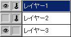
The figure above is part of the Layers panel. The "eye" mark indicates that the layer is displayed. The "key" mark indicates that the layer is locked. You can invert these marks by clicking or dragging the mark part with the mouse.
You can only select polygons of layers that are displayed and are not locked. In the above figure, only polygons in layer 3 are selected.
Edit
Editing on the control panel
![]()
Please execute "File | Create New" on the menu and press the button above to make one polygon. (Setting remains the default) It will be displayed with one polygon selected.
Next, drag left and right while holding down the push button on the lower control panel. Please change the selection state variously and drag. Make sure that only selected elements are edited.
The vertical column on the left of the control panel is "Move", the middle column is "Scale", and the right column is "Rotate".
When dragging, if you press the Ctrl button, the amount of change will be one tenth.
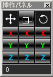
Editing with the operation panel is editing along the XYZ axes. Editing on the operation panel is powerful when creating fixed objects such as bridges and buildings arranged parallel to the Z axis.
Edit on screen
![]()
The button in the above figure is a tool for editing with the current horizontal and vertical directions displayed on the screen as axes. The axis of abscissa and ordinate on the screen changes depending on the position and viewpoint of the camera.
For example, if you want to move the object backwards with the moving tool, raise the camera position and turn it into overhead view. If you drag upwards as it is, the selected object moves to the back side, and so on.
Move
![]()
Pressing the above figure button changes to "Move mode" and the mouse cursor also changes. Dragging with the left mouse button moves the selected object. Even if you drag anything, the object will move.
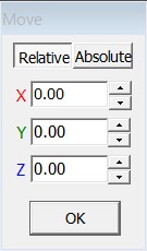
When "Move Mode" is entered, the above form will be displayed.
"Relative" displays the moving distance, "Absolute" displays the center of gravity position of the selected object.
Clicking "OK button" will move the currently selected object according to the "relative" or "absolute" mode. It is free to use, "Move by 0.1 in the Y axis direction", "Move polygon and move other polygons in the same way", "Collect selected vertices in one place".
Selection with movement tool
You can also make a selection with the movement tool. The specification of selection is the same as the selection tool, but the mechanism to cancel is slightly different.
- When moving process is executed by dragging, selection will not be canceled. When you drag and move a place with nothing, it's same.
- Clicking an element in the selected state does not cancel the selection. Even if you are not dragging it will not cancel.
- If you press the left button where is nothing and you do not drag and release the button, the selection will be canceled. You can cancel it by [Select]-[Cancel selection] of the menu.
Scaling
![]()
When pressing the above figure button, "Scale mode" is entered and the mouse cursor also changes. The operation of magnification and selection is the same as "Move mode".
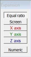
When "Scale mode" is entered, the above figure form is displayed. "Equal ratio" "X axis" "Y axis" "Z axis" is the same operation as the operation panel. I think that you can also understand "screen".
The reference position for enlargement / reduction is the center of gravity position of the selected object. So, if at least one edge is selected or at least two points are not selected, enlargement / reduction will not be executed.
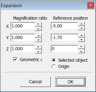
When enlarging / reducing is possible and the "Numeric" button is selected, the above dialog is displayed. In this dialog, XYZ directions of scaling can be individually specified. In addition, you can select the reference position for scaling from "center of gravity" and "origin".
Rotation
![]()
Press the above figure button to enter "Rotate mode". The mouse cursor also changes. The operation of rotation and selection is the same as "movement mode".
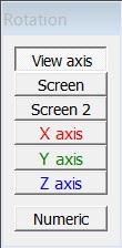
In "Rotate mode" the above form is displayed.
- "View axis" rotates around the straight line connecting the camera position and the center of gravity of the selected object.
- In "Screen", the horizontal axis is the horizontal axis of the screen, but the vertical axis is rotated using the Y axis.
- In "Screen 2", both the horizontal axis and the vertical axis are rotated using the horizontal axis of the screen's vertical axis. It seems to be close to the ball rotation of Metasequoia.
X axis Y axis Z axis works the same as the operation panel.

The above figure dialog is displayed when you select "Numeric" button. It can be rotated around the X axis, Y axis, Z axis and view axis.
Also, since the center of rotation can be the origin, you can also create the object parallel to the Z axis and rotate the entire object around the origin with the Y axis, in accordance with the rotation of the scene.
Knife
![]()
Press the above figure button to switch to "knife mode".
The knife tool adds dividing lines to polygons. It does not cut off like an actual knife.
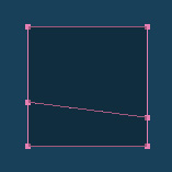
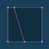
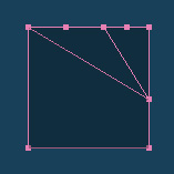
In the default setting, it is possible to divide it from the opposite sides as shown in the first and second from the left in the above figure.
You can cut it diagonally as shown in the third image by setting the "Allow knife tool to cut at slant" setting in the [File]-[Setting]-[Setting] dialog of the menu, but it isn't recommended much because the number of polygons increases very much.
Scissors
![]()
Click on the above figure button to enter "Scissors mode".
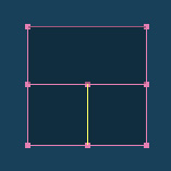
The scissors get rid of the edges that are okay if you cut it. The edge that is okay to cut off is the edge that is shared by two or more faces. In the case of the left side of the upper figure, all the edges are cut, but in the case of the right picture, only the edge highlighted in yellow is cut off.
In the default setting, when the cursor of the scissors tool gets on the edge to be cut, the color of the edge changes. Highlight display and display color can be set with [File]-[Setting].
What happens when cutting the center edge which becomes essential in the state as shown above?
The answer is as shown in the above figure. The reason to connect with the bottom face is to search the face shared and execute the process on the face found first by the scissor tool. It was due to the reason that the bottom was first found by chance that it became "the bottom".
So, there are cases like this.
Gather vertices at center
![]()
When there are two or more selected vertices, pressing these buttons sticks to those vertices. If vertexes are far apart, stick at the midpoint.
Vertices that compose the face do not stick together. It does not stick to vertices in different layers. You can do the same with [Select]-[Gather vertices at center] in the menu.
Peel off the stuck vertices
If you want to peel off the stuck vertices, hold down the ctrl key while nothing is selected, and click the target vertex. As one of vertices that became disjointed will be selected, it will be able to move.
It is also possible to separate only that face or edge by similarly selecting a face or edge.
Align in line
![]()
When there are three or more selected vertices, pressing these buttons arranges those vertices in a line. The same thing can be done by [Select]-[Align vertices in line] of the menu.
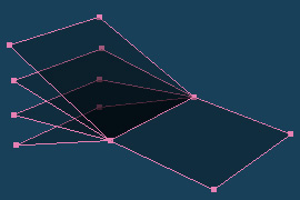
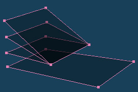
Face to camera
![]()
With the face selected, when you press this button, the selected face faces the camera. If more than one face is selected, rotate so that the average value of the normal vector of the face faces the camera.
You can use "create a polygon at the position of the 3D cursor, point the face to the camera with this button", "rotate on the viewpoint axis if it is not convenient".
The same thing can be done by selecting [Select] - [Face to camera] on the menu.
Adjust position
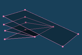
![]()
With the object selected, when you press the above figure button, the dialog shown below will be displayed.
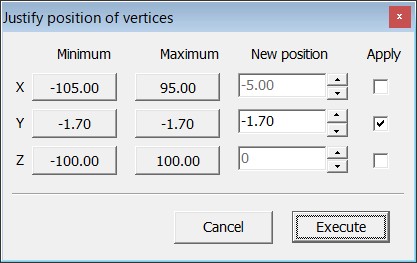
When you press the execute button, the element of the selected object is updated with the value specified in the new position for the element with the apply checkbox checked.
The minimum and maximum buttons store the minimum and maximum values of XYZ of the selected object. The new position has an average value. When the button is selected, the corresponding new position is updated with the value of the button.
"Undo" and "Redo"
Polygon editing undo redo
All edits can be restored. It can be executed by [Edit]-[Undo] in the menu. You can redo just as much as you want.
The data for restoring is writing all the polygon data to the memory. All data is written by just selecting one vertex. It might be said to be cutting corners, but the order of the layers has changed, the layer's Visible, Locked has changed, etc. are also recorded. Even when making complex choices you can go back and forth between selected states.
In my environment (Pentium 4 2.8 G memory 2 G), it seems to work lightly up to 1,200 polygon edits. When it exceeds 1,600 sheets, it starts to become slightly heavy.
If you are concerned about memory consumption, you can erase the data with [Edit]-[Clear Memory]-[History(H)] in the menu. The current consumption memory is displayed in the history item.
3D cursor moving undo redo
Also the "Undo" and "Redo" functions are added to the movement of the 3D cursor.
JOYA 2016/11/26 Since 2016/11/26