Memo of making the airplane model cricri for RealFlight by Blender 2.49b (1)
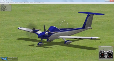
This is a memo of creation of 3D model when I made the airplane model cricri for RealFlight G3.5 from a 2D drawing figure only by free software.
Next page Last page
Old-edition Rev.1: How to make the box type airplane for Real Flight G3.5 by free software
Information of the real cricri: http://www.cricri.zoomshare.com / 0.html (external link)
"|" means "OR". For example [x|y|z] means to press "x" or "y" or "z" key.
cricri example data: for Blender : cricri.zip , for RealFlight G3.5 : cricri_EA.G3X 、 for RealFlight 8~Evolution : cricri_RFX.zip
1. Outline of Procedure
The aircraft model for RealFlight is made by 3ds max. But 3ds max is very expensive. Then, rayvel and maxtop make a python script for Blender. Here, an original airplane model is made by using this script only at free software. However Knifeedge supports only 3ds max. Please accept there is an unsolvable problem in blender. I expect Knifeedge to support for Blender 2.6x even at non-guarantee, because 3ds max free is for education and expire in 3 years.
Blender 3DS export project :http://www.knifeedge.com/forums/showthread.php?t=17674
Using "RealFlight FBX Exporter" made by robertlong 13, you can make a model for RealFlight 8 in Blender 2.79b. Except for file export, it is almost same method as this article. http://bigarrow.tea-nifty.com/blog/2018/09/realflight8-and.html
1) Preparation of 2D drawing
Prepare a 2D drawing file. You may make 3D model directly without a 2d drawing. A file format is png, jpg, tga, etc.
-
Search on the Internet.
-
Scan a 2d drawing of paper with a scanner or a camera.
-
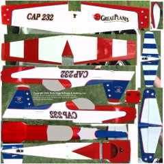
Take a photograph of an actual airplane. It can also be used for a texture, if it has no shadow. The following picture is a texture file for an airplane of RealFlight G3. It turn out a photograph because a arm comes out. ( It was corrected as erasing shadows and makig a canopy transparent. )
-
Create 2D by CAD. There are JW CAD, DraftSight, etc. as free software.
2) Create 3D model by Blender.
-
Create 3D model (face form) with 2D drawing. (You may create without 2D drawing dilrectly.)
-
Create a developed figure of surface from 3D model. (It will be used as guide for making the following texture file.)
3) Creation of a texture
Read the developed figure of 3D model, create the texture (paint of the surface of the airplane) by reference to it. The texture file format shall be .tga.
4) Perform setup of 3D model by Blender.
-
Assign a texture on 3D model.
-
Set up the axis of rotation of rotating things, such as a moving blade, a propeller, and a wheel etc..
-
Specify the order of attachment of each part.
5). Creation of a .kex(G3.5) or .fbx(8~Evolution) file
-
Execute export_3ds2kex.py from blender menu and create .3ds and .sup files.
-
Create .kex file from .3ds and .sup files by 3ds2kex.exe. (It is also possible to perform export_3ds2kex.py and 3ds2kex from blender at one time and to create .kex file)
* For RealFlight 8~Revolution, do not use export_3ds2kex.py and 3ds2kex. Run RealFlight FBX Exporter from Blender to create .fbx file.
6) Read by RealFlight and set up the flight characteristic.
Read a kex file by RealFlight, correct the flight characteristic and complete.
2. Soft Download and Installation
The script which outputs the file for RealFlight does not work on the blender after 2.5, because the specification of blender was changed a lot. Then I introduce the way of installation which both 2.49b and after 2.5 can be exist. And I introduce export_3ds2kex.py and 3ds2kex.exe. Installation of Inkscape and GIMP are omited here because it is just to double clickfor installation.
1)Python 2.66 (G3.5)
It is software required to run Blender. Python2.6x is confirmed to work with Blender 2.49b.
-
Click [DOWNLOAD] on the left-hand side of the following URL, click [Releases][2.6.8][The last binary release of Python 2.6 was 2.6.6.], download [Windows x86 MSI Installer (2.6.6) (sig)], and it installs by default. (2.66 is the object version of the last of 2.6 systems. Only source is published after 2.67.)
http://www.python.org/ (external link)
2)Blender 2.49b (G3.5)
-
Dowmload [Download][Older versions][http://download.blender.org/release][Blender2.49b][blender-2.49b-windows.zip] from the page of the following URL.
http://www.blender.org/ (external link)
-
Uncompress the downloded file and move it to a suitable folder (example "C:\Program1\blender249b").
- Create blender249b.vbs by text editor. Contens are followings. Change the path to installed path of Python and Blender.
Option Explicit
Dim shell
Set shell = WScript.CreateObject("WScript.Shell")
Dim env
Set env = shell.Environment("USER")
env.item("PYTHONPATH") = "C:\Python26;C:\Python26\DLLs;C:\Python26\Lib;C:\Python26\Lib\lib-tk"
Dim arg1, pname
if WScript.Arguments.count = 0 then
    pname = """C:\Program1\Blender Foundation\Blender249\blender.exe"""
else
    arg1 = WScript.Arguments(0)
    pname = """C:\Program1\Blender Foundation\Blender249\blender.exe""" & " " & arg1
end if
shell.Run pname
env.Remove("PYTHONPATH")
Set shell = Nothing
-
Right-click "blender249b.vbs" which moved, click [Create Shortcut (S)], and change the name of the created "blender249b.vbs - shortcut" to "Blender249b", and move it to a desktop.
-
Blender2.49b is started by drags and drops .blend file to the shortcut of Blender249b now.
-
If you want to relate ,blen with Blender2.49b, right-click a .blend file and click [Open from program], check [Always chose when opening this kind of file (A)], click [Refer (B)], select blender.exe under "C:\Program1\blender249b", click [Open (O)]. From next time, Blender2.49b run by double clicking a .blen file.
* There isn't a central button function in Logicool SetPoint 6.32 software for Logicool mouse. If a center button of mouse can't be used, view point can't be rotate in blender.
Measure: Download and uncompres the following URL to SetPointPlus, right-click v6.bat, and execte it as an administrator. After it was done, a central button can be selected with the menu of SetPoint.
http: //d.hatena.ne.jp/wwwcfe/20090901/SetPointPlus (external link)
There is also the following, but I haven't checked it.
http://uberoptions.net/ (external link)
For RealFlight 8~Evolution : Blender 2.79b
For RealFlight 8~Evolution, Blender 2.49b and Python 2.66 are unnecessary. Please install the Blender 2.79b instead.
https://www.blender.org/download/releases/2-79/
3. Add KEX Creation Function to Blender.
It's set to be able to output ".kex" automatically when outputing ".3ds" and ".sup" by clicking [User Preferrence]Windows - Menu[File]-[Export]-[3D Studio 2KEX (.kex)] of blender.
1) Installation of export_3ds2kex.py (G3.5)
It is able to output a .3ds file and .sup file.
-
Downlosd the attached file of the report of #72 (or #73) of the following URL.
http: //www.knifeedge.com/forums/showthread.php?t=17674&page=5&pp=15 (external link)
Download of an attached file requires Log in to Knife Edge Forum. When not having registered, clik [register] under a Log in screen and registrate. Registration is no charge.
-
If export_3ds2kex.g3x is downloaded, change the extension to .zip and extract it. If export_3ds2kex is downloaded, change the extesion to .py.
* : If export_3ds2kex.py is UTF-8 form, it will not be displayed on the menu of blender. In this case, delete 3 bytes (EF, BB, BF) of a file head, so that it is made for "#!BPY" to come first.
-
Save export_3ds2kex.py at the script folder of blender.
Example of a script folder:
-
C:\Program Files\Blender Foundation\Blender\.blender\scripts\ : When it installs in Windows XP (32 bits) by an exe file
-
C:\Program1\blender249b\.blender\scripts\ : When a zip file is extracted to C:\Program1\blender249b\
(export3ds2kex by barbolani : https://github.com/barbolani/export3ds2kex)
2) Installation of 3ds2kex.exe (G3.5)
Specify the folder where 3ds2kex.exe which creates .kex file from 3ds file and .sup file by Blender is saved. Thereby, .kex can also be simultaneously created now by the Export operation from Blender.
-
Go to the following URL, click [KEmax]-[Downloads], download "KEmax 3ds->kex Converter". and copy the extracted files to "C:\KEMAX.".
After RealFlight G4, "KEmax 3ds->kex Converter - BETA" is used.
http://www.knifeedge.com/ (external link)
-
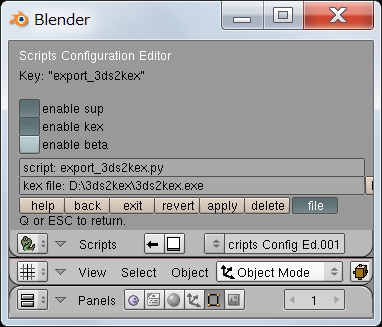
Click [Script Window]-[Scripts]-[System]-[Scripts Config Editor]-[Export]-[3D Studio 2KEX (3ds)], turn on [enabel sup], and [enable kex]. Click the button at the right end of [kex file:], select "3ds2kex.exe", and click [Choose file]-[Q|.Esc].
Reference information: http://www.knifeedge.com/forums/showpost.php?p=96939&postcount=19 (external link)
* Refer to attachment pdf file"Blender_tutl.pdf.rfx" of the following URL in detail.
http://www.knifeedge.com/forums/showthread.php?t=28009 (external link)
* When a collision mesh is created, .kex file created by [Export] cannot be used. Edit .sup file by below-mentioned "edit .sup file page" and re-create .kex.
For RealFlight 8~Evolution : Installation of "RealFlight FBX Exporter"
"export_3ds2kex.py" and "3ds2kex.exe" aren't needed for RealFlight 8~Evolution. Instead, use "RealFlight FBX Exporter".
- Download "Instead, use "RealFlight FBX Exporter"" made by robertlong13.
https://github.com/robertlong13/io_scene_realflight/releases/tag/0.2.1
- Move the io_scene_realflight-master folder where you extracted the addons folder of the blender. Exampe : C:\Program1\blender-2.79b\2.79\scripts\addons
- Launch Blender (2.79b) and open Use Prefereces from the window menu in the upper left.
- Open the Add-ons tab.
- Press the Refresh of the above.
- Press Import-Export on the left.
- Import - Export: RealFlight FBX export will be displayed in the list, so check it.
- Press the Save User Settings of the above.
In the site below, it is written that the retractable gear does not work with RealFlight9, BLENDER 2.83 and REALFLIGHT FBX EXPORTER 0.3.1.
REALFLIGHTの機体を作る(メモ) : https://www.catv296.ne.jp/~myergo/rf_model.html (external link)
4. Useful tool for Modeling
Model creation is possible even if it does not use following tool. If downloaded .py file is stored in the script folder of Blender, it will come to be displayed on the menu of Blender. Only Align View is used in this example.
1) Align View
A viewpoint is changed into the XYZ axis of the object selected in object mode. It uses to transform the leaning object along leaning axis of the object. This operation is like the Object Mode version of [Shift]+[v] operation in Edit Mode.
http://airplanes3d.net/scripts-020_e.xml (external link)
2) Geom Tool (reference)
Move a vertex on a face or edge. It is used when you want to fit two objects on thier face or edge. It can be used on 2.49b, it is for 2.48a though. Since it is necessary to select a vertex and face, select two objects with pushing shift key in object mode, click two or more select mode buuons with pushing shiftkey in edit mode.
http://glender.hybird.org/ (external link)
3) Cross Section (reference)
Create a edge and vertices on a cross edge of two faces. FOr exzmple, it is used when attaching the square hatch on the cylindrical body. The difference from boolean is that the created mesh is independent from the original mesh.
http://airplanes3d.net/scripts-030_e.xml (external link)
5. Preparation of 2D drawing of Airplane
-
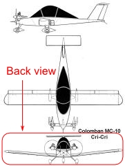
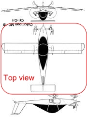
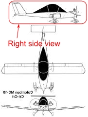
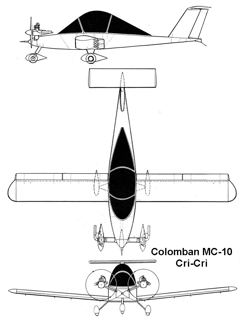
Prepare the 2D drawing of cricri.
Example of a download site:
http://themekgpproject.com/gallery/2/thumbnails.php?album=58&page=2 (external link)
http://richard.ferriere.free.fr/3vues/cricri_3v.jpg (external link)
http://www.rcgroups.com/forums/attachment.php?attachmentid=2411897 (external link)
-
Rotate or reverse a 2D drawing.
Created 3D model direction is, that the nose is upper in top view, the tail is near side in front view, the right side is near side (the nose is right) in side view for realflight. It is impossible to rotate the back ground in blender, so in this example, read the downloaded picture by a paint software (example: GIMP, IrfanView), rotate it 180 degrees, save it for top view, flip it horizonal, save it sife view. There is no tail view in 2D drawing, use front view instead of tail view.
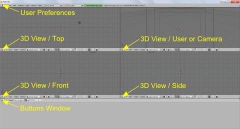
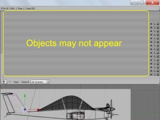
6. Window layout of Blender
-
Run blender.
-
Push [x], left-click [Erase selected Object (s)], to remove the first six face pieces and change into the state where there is nothing.
-
Right-click on the boundary of up-and-down window, left-click [Split Area], left-click the center of upper window, to devide upper window into two.
-
Right-click on the boundary of devided windows, left-click [Split Area], left-click the center of left window, to devide left window into two.
-
Right-click on the boundary of window devided into two right and left, left-click [Split Area], left-click the center of right window, to devide right window into two.
-
Move a mouse on the upper left window, push [7]. Move a mouse the lower left window, push [1]. Move a mouse on the upper right window, push [0]. Move a mouse on the lower right, push [3]. Then top wiew, front view, camera view, side view ara displayed.
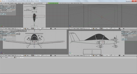
7. Display 2D drawing as a sketch
-
Move a mouse on the upper left window, push [Ctrl]+[Up], to show only top view.
-
Left-click [view], left-click [Background], left-click [Use Background Image], left-click [Load], left-click the button under [P] at upper left, left-click the drive where 3D drawing is, left-click the folder where 2D drawing is, left-click 2D drawing, left-click {SELECT IMAGE] at upper right, 2D drawing is desplayed.
-
[Size:5.00] is displayed in the [Background image] dialog box. This means that the length from center of image to left or right edge is 5BDU(Blender unit) = 5inch = 12.7cm.
It is found out that the length of main wing is about 9.5BDU = 24cm from grid. If you want to make the length of wing about 140cm, it is necessary to magnify background image 140cm/24cm = about 6 times. Therefore change previous [Size:5.00] into [Size:30].
-
Left click [X Offest] or [Y Offset] of "Background Image" dialog box to move center-of-gravity into 3D cursor. In addition, if left-click a number and put a number in from a keyboard, it can tune finely by 0.01 unit.
-
Push [Ctrl]+ [Down] to return to the original Window display.
-
Display a front view in lower left window, display a side view in lower right window by the same way as above. If it cannot be displayed, move a cursor on the such window, push [5] to change a display method from perspective to a rectangular system (toggle operation).
* The direction of arrangement
-
Top view [7]:a nose of an airplane is upper, a top of an airplane is near side. Front view [1]:nose of an airplane is far side, top of an airplane is upper. Side viwew [3]:nose of an airplane is right, top of an airplane is the upper. (It differs from FMS)
* The relation of the scale of Blender and RealFlight
-
1BU(Blender Unit) = 1-inch (inch) = 25.4 mm
(1BU(Blender Unit) = 1 m for RealFlight 8~Evolution)
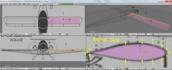
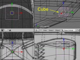
8. Creation of 3D Model
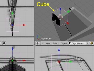
1) Creation of the body
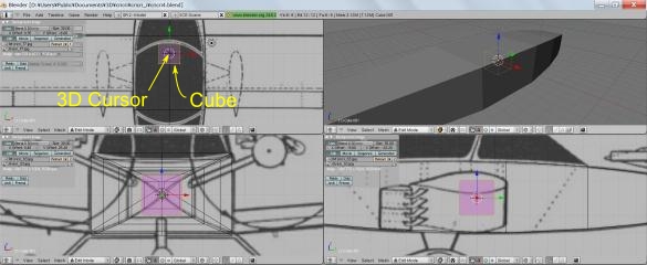
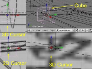
Since the fuselage of cricri is a box type, it creates based on Cube.(In the case of a round fuselage, it creates based on Cylinder)
-
Move a mouse on upper right window, push [Shift]+[a], left-click [Add]-[Mesh]-[Cuve], a cuve is added.
-
Left-click the draw type button, left-click [Wireframe].
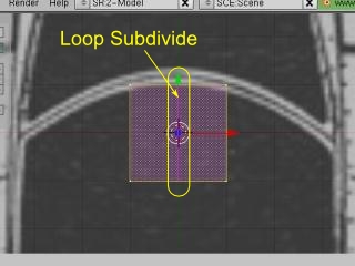
Push [Tab]-[Ctrl]+[r] and left-click, click a middle button of a mouse for finishing loop cut. (Or push [0]-[Enter])
-
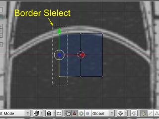
Push [Ctrl]+[Tab] for changing "Select mode" to [Faces] (or [Vertices]).
-
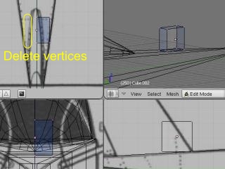
Push [b], drag a mouse with right-click so that deleting vertices is surrounded by range selection.
-
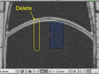
Push [x], Left-click [Faces](or [Vertices]), to erace a half.
-
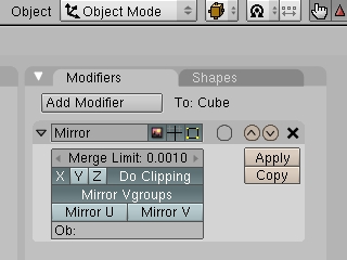
Push [Tab] to change to "Object mode", left-click [Add Modifier] of a "Modifiers" tab, to display a mirror. Left-click [Do Clipping] of "Modifier" to avoid going to the side opposite to from a center.
-
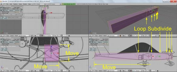
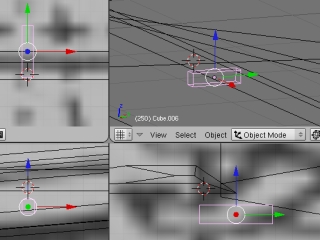
Push [Tab] to change to "Edit mode", push [a] twice to deselect all, push [b], select vertices, push [g]-[x|y|z], move vertices. Or drag the red or green or blue arrow which called a manipulator by left-click. Fit the outline of the cube object to the fuselage by this way.
-
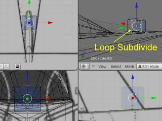
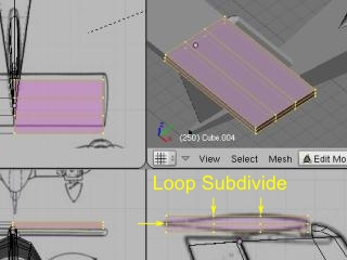
Push [Ctrl]+[r], left-click to fix that devision number is one, move a mouse to division point, left-click a mouse to determine the division point. If you want to devide at an equal interval, push [Clrl]+[r], rotate a mouse wheel to select division number, move a mouse to select a division direction, push a middle button of a mouse to complete. In this example, put the three dividing point the back end of a wing, a forward end, the forward end of a canopy, and the nose which has small curvature.
-
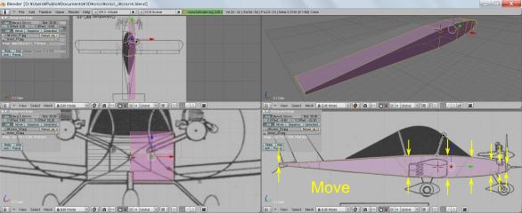
Push [Ctrl]+[Up] at lower right window to make it the full screen. (Returning is to push [Ctrl]+[Down].)
-
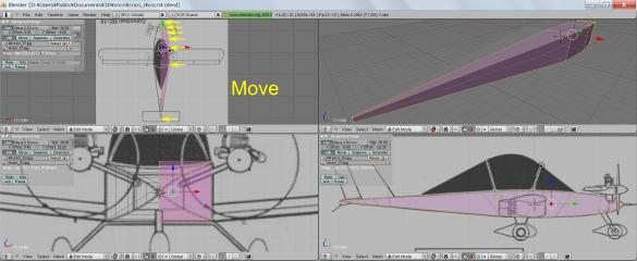
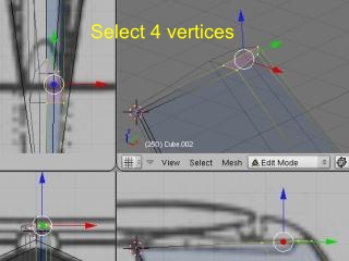
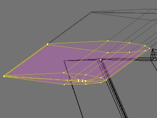
By the same way as fit the size of the whole cube, select the pair of vertex which include far side vertex one by one, push [g]-[x|y|z] and move a mouse , or drag a manupulator by left-click, so that fit the cube object to outline of the fuselage.
g a manipulator by left-click, and unites the size of Cube object with the outline of the body.
-
Push [Ctrl]+[Down] to return to the original screen, and then fit the size of cube with the outline of the fuselage in a similar way in an upper left top view.
The body is completion above. If there is no necessity for camfering of the fuselage, go to creation of a wing.
If you are new of creating an aircraft model for RealFlight, it is recommended to creat only a fuselage and check that it can be displayed in RealFlight. If an error occurs after all object created, it is difficult to find out the wrong procedure.
Notes of modeling
-
When you use scaling [s] and rotation [r], be sure to grasp the origin point of operatin and the direction of the axis to operate. Specifically, grasp [Pivot], [Orientation], a cursor position, [[Shift]+z|y|z].
-
It is better to use scaling [s] not by Object Mode but by Edit Mode. It may become unusual when what carried out scaling by Object Mode is rotated by Edit Mode. However, it is no problem to use scaling [s] in object mode when the object isn't rotated in edit mode.
-
It is better to rotate the whole object not by Edit Mode but by Object Mode.
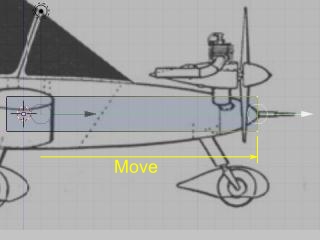
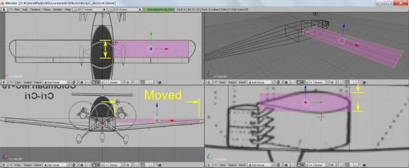
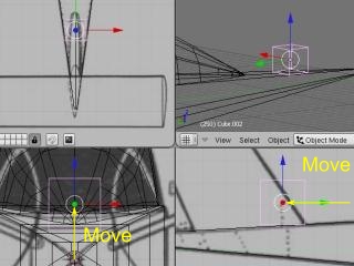
Move a camera
The whole aircraft is not displayed on an upper right screen, because a camera it too close to it. Then move a camera. Although moving by [g] is possible, will move a camera to view point now here.
-
put a mouse cursor on an upper right window, push [0], [5], and [5].
-
By the mouse wheel, the inside button drug, and the button drug in [Sift]+, a viewpoint is moved so that the whole body may be displayed in the center.
-
A camera is moved to the present viewpoint by [Ctrl]+[Alt]+ [0].
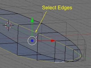
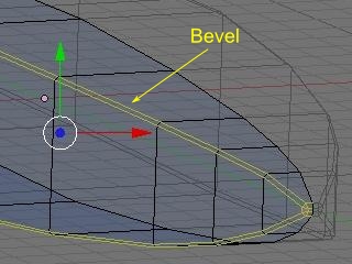
The body is cuted off the corners.
-
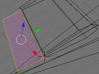
Since a little apical portion of the body of cricri is round, it can cut off the corners by [W] and [Bevel] after choosing the neighborhood [ pushes the button of the neighborhood at the lower right of 3D Window, or ] to make into neighborhood selection mode and cut off the corners by [Ctrl]+[Tab]+ [2].When cutting off the whole the corners, [Buttons Window], [Modifiers], [Add Modifier], [Bevel], and [Width:0.1000] may be sufficient.
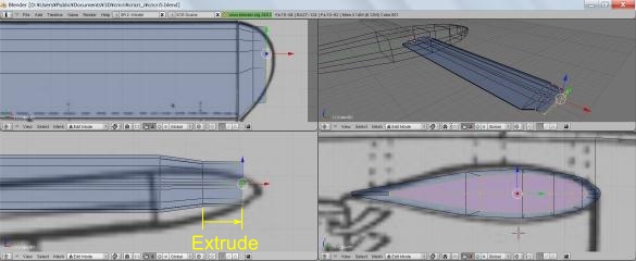
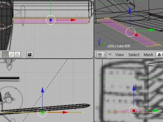
2) Creation of a wing
If it refers to Youtube with "Blender Airplane" etc., how to make many is introduced.As for a wing, if this is seen, it is common to lengthen and to make from the body.This gentleman tends to make a fillet.However, since cricri does not have a fillet, it makes from another Cube.
-
Object Mode is used by [Tab], a mouse is moved to upper right Window, the full screen is used by [Ctrl]+ [↑], a cursor is reset at the starting point by [Shift]+ [c], a viewpoint is moved by [c] focusing on a cursor, and it is made a suitable magnifying power with a mouse wheel.(Since the origin of Cube created later is set to x= 0 by this, a wing on either side can be created by a mirror.)
-
[Shift]+ [a] is pushed, [Add], [Mesh], and [Cube] are left-clicked, and six face pieces are added.
-
using Edit Mode by [Tab] -- [a], [b], and [g] -- [x|It unites with the outside of the right wing by y].
-
A mirror is used by [Add Modifier] and [Mirror] of a Modifiers tab of [Tab] Buttons Window.
-
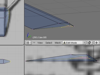
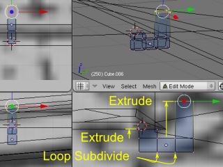
using Edit Mode by [Tab] -- [Ctrl]+ [r] -- MouseWheelUp(ing) -- it is decision by selection and right-click to 5 about the division number of a transverse direction.It decides by two division and inside button click in [Ctrl]+ [r] and a lengthwise direction at the middle point.
-
[a][b][s|It unites with the cross-sectional outside of a wing by g] and [z].
-
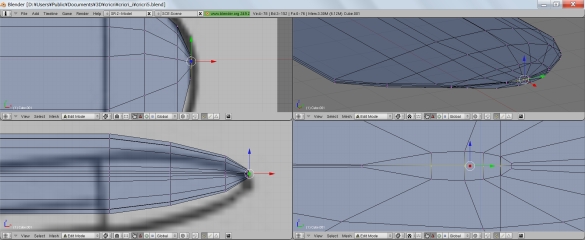
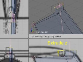
If the position which chooses an aerofoil tip by [a] and [b], and extends the [e] and [Region] aerofoil tip is decided, it will decide by left-click.
-
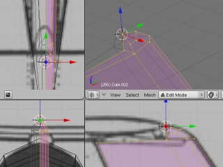
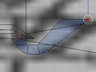
[Pivot] is set to [Median Point] by lower left 3D Window, and it reduces to a y-z plane by [s] and [Shift]+[x], and decides by left-click.An order position is corrected by [g] and [y].A repetition aerofoil tip part is formed for enlargement, reduction, and movement a total of 3 times.
* It is grasping where the starting point of scaling having become, when using scaling [s].
-
The central point of the field of an aerofoil tip is chosen, and x shaft orientations are moved and made to a few in accordance with an outside by [g] [x].
-
Edit Mode is used by [Tab], [Pivot] is set to [Median Point] by lower left 3D Window, and it unites with a dihedral angle by [r] after all the selections by [a].(After not uniting a dihedral angle here but creating an aileron, the direction of a work procedure rotated together decreases.)
-
In order to unite coordinates with inclination of Cube, [Pivot] is made into [Active Vert/Edge/Face] and [Orientation] is set to [Normal].
-
[a][b][g][yy|It unites with the outside of a wing by zz].
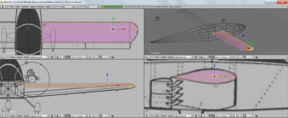
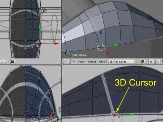
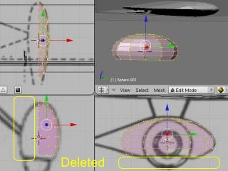
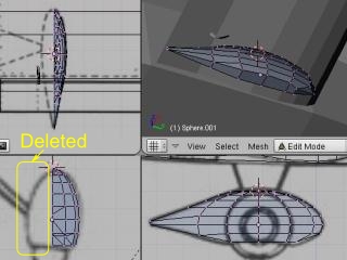
3) Creation of a canopy
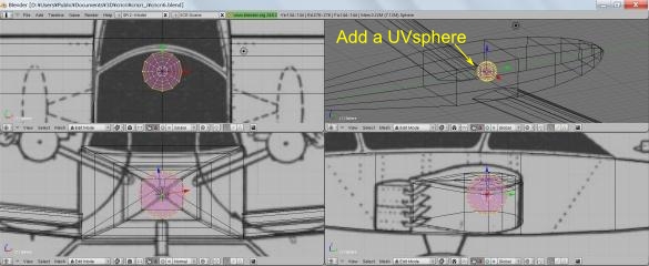
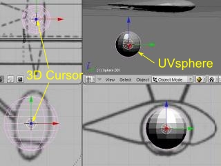
Although it is common in the example of Youtube to lengthen and to make from the body, it creates based on UVsphere here.
-
Object Mode is used by [Tab] and a cursor is reset at the starting point by [Shift]+ [c].
-
[Shift]+ [a] is pushed, [Add], [Mesh], and [UVsphere] are left-clicked, both [Segments] and [rings] are set to 12-16, and it is [OK].
-
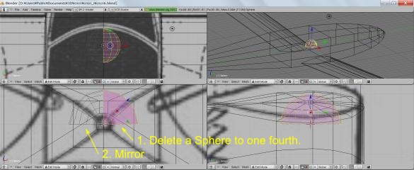
Edit Mode is used by [Tab] and it is made to rotate 90 degrees by [r] [x] [90].
-
It leaves selection [x] [Vertices] for the [a] and [b] lower half, leaves the upper right 1/4 for the [b] left half by selection [x] [Vertices], and erases a surface of a sphere.
-
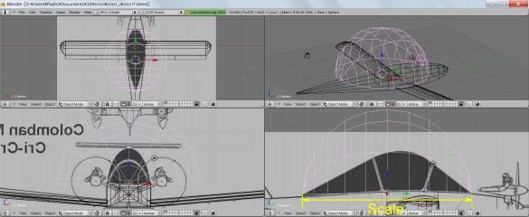
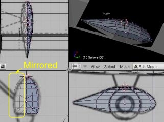
A mirror is used by [Add Modifier] and [Mirror] of a Modifiers tab of [Tab] Buttons Window.
-
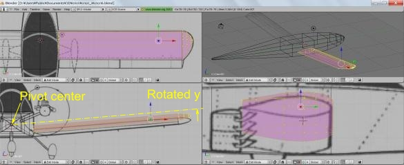
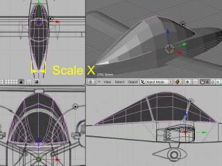
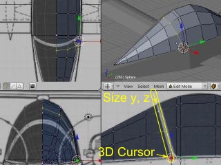
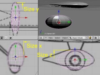
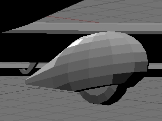
In order to lessen distortion of a surface of a sphere as much as possible, the form of the ball itself is not changed by Object Mode, but only a size and a position are changed by [g] and [s], and the same size as the length of a canopy is chosen.
-
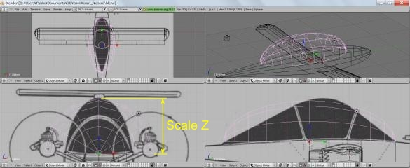
[s] Only the Y-axis is fixed by [Shift]+ [y] and the height of a ball is united with the height of a canopy.
-
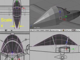
[s] Only the X-axis is made variable by [x] and the width of a ball is united with the width of a canopy.
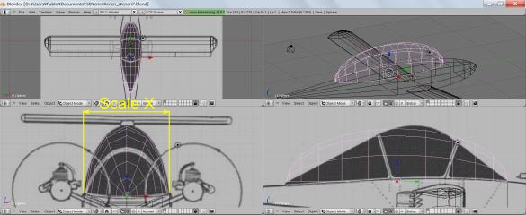
-
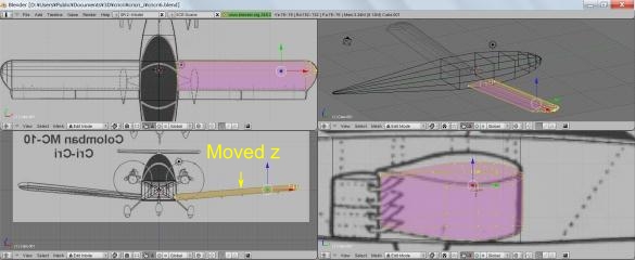
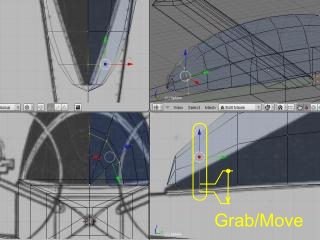
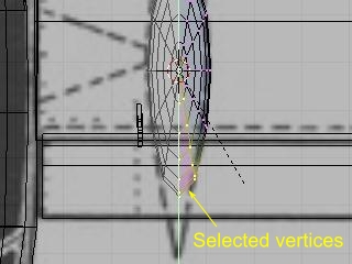
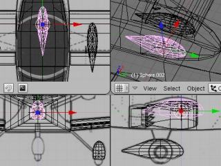
The all points of the 3rd vertical section are chosen from back by [a] and [b] by Edit Mode, and it moves so that a lower point may become a position of the surface of the body by [g] and [z].
-
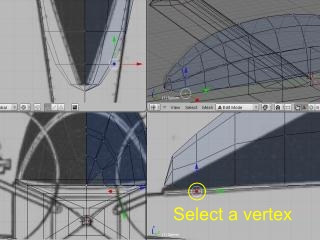
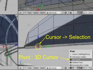
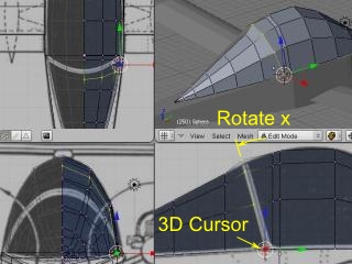
Only the point of the 3rd bottom is chosen by [a] and [b], and 3D cursor is moved to the bottom point by [mesh], [snap], and [Cursor -> Selection].(Shortcut is [Shift]+ [s] and [4])
-
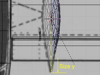
The [Pivot] button of lower right Window is pushed and the reference point of scaling is set as [3D Cursol].
-
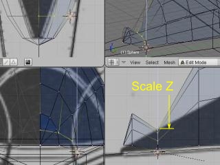
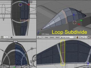
The all points of the 3rd vertical section are chosen from back by [a] and [b], and scaling is carried out so that the upper point may become a position of the upper surface of a canopy by [s] and [z].
-
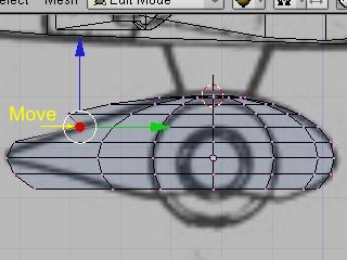
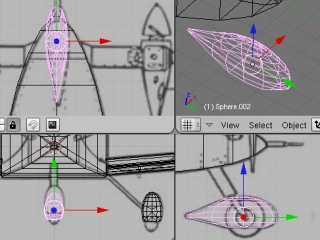
The above is repeated and the section of the lengthwise direction of a canopy is united with a sketch.
-
A transverse direction as well as a lengthwise direction is united with a sketch.Since the reference point of scaling of a transverse direction is the center of the body, it chooses only the point based on bodies by [a] and [b], and moves 3D cursor by [mesh], [snap], and [Cursor -> Selection] centering on the body.(Shortcut is [Shift]+ [s] and [4]) Unlike a lengthwise direction, it is not necessary to reset up a cursor after this.
-
The point of a horizontal line is all chosen by [a] and [b], the work which unites an outside with a sketch and goes by [s] [x] is repeated, and the outside of a transverse direction is united with a sketch.
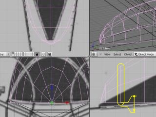
Creation of a window frame (method 1)
Although a canopy is completion above, if the mesh is created according to the window frame, it can be made a guide later and the texture of a window frame can be drawn.However, a good method cannot imagine.A canopy is somewhat uneven in case of the following methods.
-
A window frame is perpendicularly created by [Ctrl]+ [r] per root of a window frame.
-
Only the point of the bottom of a back window frame is chosen by [a] and [b], and 3D cursor is moved to the bottom point by [mesh], [snap], and [Cursor -> Selection].
-
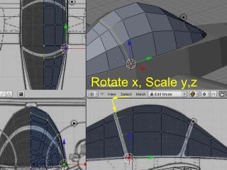
A back window frame is chosen by [b].[r] A superior extremity is united with the position of the cross direction of a sketch by [x].
-
Scaling is carried out so that the upper point may become a position of the upper surface of a canopy by [s] and [z].If not suited, [r] [x], [s], and [y] are repeated and it unites with a sketch.
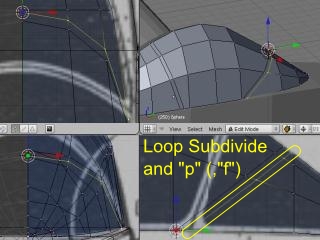
Creation of a window frame (method 2)
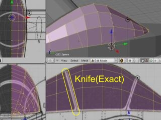
In the above-mentioned example, although the window frame was perpendicularly rotated aslant after creation, the method here creates a window frame aslant from the beginning by a knife function.although this is also uneven a little -- a front method -- merit -- that is right.
-
[a] is pushed by Edit Mode, a canopy is all chosen, [k] is pushed, and a click and [Enter] are pushed for two points so that Knife (Exact) and a window frame edge may be met.
-
Only the point of the bottom of added 窓縁 is chosen and 3D cursor is moved by [shift]+ [s] and [Cursor -> Selection].
-
The point of 窓縁 is all chosen by [b].
-
Scaling is carried out by height, [s], and [y] by [s] and [z] at a cross direction, and 窓縁 is united with a sketch.
-
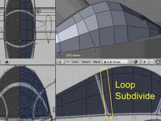
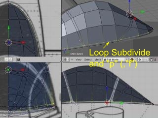
Parallel are used at 窓縁 which moved the mouse and was previously created by a left-click and [p] so that the neighborhood may be displayed in the direction which already becomes 窓縁 of one of the two by [Ctrl]+ [r] (if it becomes parallel the reverse neighborhood, it will change by [f]), and according to a sketch, it decides by left-click with a mouse.
-
After clearing selection by [a], only the point of the bottom of added 窓縁 is chosen and 3D cursor is moved by [shift]+ [s] and [Cursor -> Selection].
-
After clearing selection by [a], the point of added 窓縁 is all chosen by [Shift]+ right-click.
-
Scaling is carried out by height, [s], and [y] by [s] and [z] at a cross direction, and 窓縁 is united with a sketch.
-
The edge by the side of an instruments panel is created similarly.A lower window frame is created by [Ctrl]+ [r], [p], and [f].
It seems to be troublesome although the method of using Boolean is also considered.Using Cross Section introduced with the tool useful for modeling, how to create a window frame aside from a canopy is also considered, but he needs to be conscious of which shall come out on the surface between a canopy and a window frame.
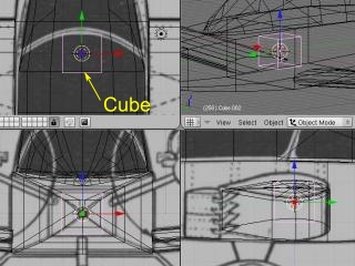
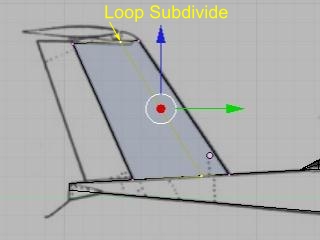
4) Creation of a vertical tail
-
Object Mode is used by [Tab], 3D cursor is reset by [Shift]+ [C], and it displays focusing on 3D cursor by [C].Pivot is set to [Median Point] (shortcut is [Shift] or {Ctrl]+[and]), and a manipulator is displayed on the center of an object.
-
Six face pieces are added by [Add], [Mesh], and [Cube], the manipulator of z or a y-axis is dragged, and the front lower side is united with the forward end bottom of a vertical tail.
-
The button of Draw type is left-clicked and [Wireframe] is left-clicked.
-
A [Tab]+ [ [Ctrl]] [r] left-click and the inside button of a mouse are clicked by Window of the upper left or the lower left.(Or [0] is pushed and it moves to the middle point, and [Enter] is pushed and it decides.)
-
[Ctrl]+[Tab] is pushed and "Select mode" is changed to [Faces] (or [Vertices]).
-
Range selection is dragged and made by right-click so that [a] and [b] may be pushed and the point to erase may be surrounded.
-
([x] and [Faces] -- or left-click [Vertices] and erase a half.
-
[F9] is pushed, "Panels" is made into "Editing", [Add Modidier] of a "Modifiers" tab is left-clicked, and it indicates by a mirror.Moreover, [Do Clipping] of "Modifier" is pushed so that it may not go to the side opposite to from a center.It returns to Edit Mode by [Tab].
-
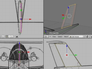
The outline of six face pieces is united with the vertical tail of a sketch using [a], [b], [g], etc.
-
The loop cut neighborhood is moved to the position to which a point comes for the angle of the forward end part of a horizontal stabilizer by [Ctrl]+ [r] left-click, and it decides by left-click.
-
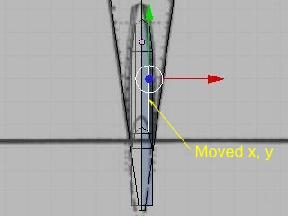
Lower right [Edge select mode] is pushed, the manipulator of selection, x, and a y-axis is dragged for forward right 縦辺 by right-click, and the form of a front tip is prepared.Next, a right rear trailing edge is right-clicked, the manipulator of an x-axis is dragged, and width of a trailing edge is narrowed.
-
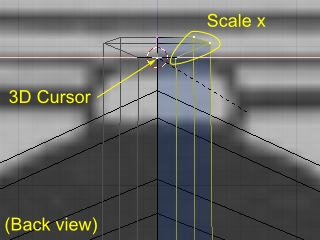
In order to carry out scaling centering on the body, lower right [Vertex select mode] is pushed, the point on the central line of the body is chosen by right-click, and 3D cursor is moved by [shift]+ [s] and [Cursor -> Selection].The [Pivot] button of lower right Window is pushed and the reference point of scaling is set as [3D Cursor].
-
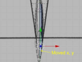
The point of a superior extremity is all chosen by [b], and width of a superior extremity is narrowed by [s] [x].
-
Four points of the upper surface of the vertical tail in front of a horizontal stabilizer are chosen by [a] and [b], and it extends up by [e], [Region], and [z].
-
[g|s][x|y|The extended point is prepared using the function of z].
5) Creation of a rudder and an elevator
An elevator is created in the point of a rudder and a wing by the way of a vertical tail.After a rudder carries out division deletion and carries out a mirror to right and left, division by loop cut is not carried out, but is made to only transform an outside.An elevator carries out division deletion at right and left, is divided into three after a mirror in two division and order at length, and creates the section of a profile.After extending an aerofoil tip once, it only carries out reduction movement.
6) Creation of an aileron and an aileron hinge
-
Since an aileron is created by a mirror centering on the body, in order to move an origin to a body center, six face pieces which reset 3D cursor by [Shit]+ [c] first, and have an origin in a body center by [Add], [Mesh], and [Cube] are created.
-
Edit Mode is used by [Tab] and it is [a] [g] [x|.y|It unites with the outside of an outline aileron using z] etc.In addition, since a width direction will shift if a dihedral angle is attached later, it is not necessary to unite the width direction strictly.
-
An aerofoil tip is chosen by [a] and [b], and it extends by [e], and unites with the outside of an aerofoil tip by reduction, [g], and [y] by [s].
-
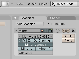
The left aileron is generated by [Modifiers], [Add Modifier], and [Mirror].
-
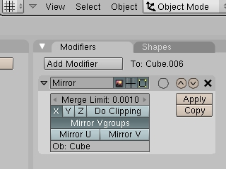
Since yz plane which the origin of an aileron has will also rotate if it is made to rotate by Object Mode as it is, if the right wing goes up, the left wing will fall.Since an origin does not rotate, both wings go up by Edit Mode.Here, in order to make it rotate simultaneously with a hinge by Object Mode later, the starting point of Mirror is set as the body by inputting object name "Cube" of the body into [Ob:] of [Modifiers] and [Mirror], and pushing [Enter].
(1) Creation of an aileron hinge
Since there is an aileron hinge by a total of eight right and left, one is created and others are created by the mirror and a link copy.However, it is unrealizable if the origin of a mirror and a link copy is inseparable.Then, the starting point of a mirror is set as other objects.Specifically, the body is made into the starting point of a mirror.
-
It left-clicks in the position which creates a hinge, and moves 3D cursor.Six face pieces are created by [Add], [Mesh], and [Cube].
-
[s][g][x|y|An outline size is united by z] etc.
-
It goes into Edit Mode by [Tab], and divides into three by [Ctrl]+ [r], the upper surface of order is lengthened up by [e], respectively, and it is made a 凹字 type.
-
[a][b][g][y|A form is prepared by z].
-
Object Mode is used by [Tab], object name "Cube" of the body is inputted into [alumnus:] by [Modifiers], [Add Modifier], and [Mirror], and it is [Enter].
-
[Object], [Duplicate Linked] (shortcut is [Alt]+ [d]), and the object copied by [g] [x] are moved.If this is repeated and the hinge of four one side is created, it will be automatically generated by a mirror also at the side opposite to.
Since the same dihedral angle as a wing is given to an aileron and a hinge, the dihedral angle of a wing is measured.
-
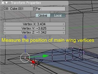
A wing is chosen by right-click, Edit Mode is used by [Tab] and only one corner point of the neighborhood which measures an angle is chosen by right-click.
-
Coordinates are displayed by [n] and a note of x and y coordinates is made.A note of the coordinates of an end is already made in a similar manner.A dihedral angle is calculated by arctan (y2-y1) (/x2-x1) using a mathematical calculator or spreadsheet software.
The table which asks for an angle from coordinates: 3d_angle.xls (use is possible at LibreOfficeCalc (no charge))
-
Object Mode is used by [Tab], an aileron and a hinge are all chosen by [Shift]+ right-click, and a dihedral angle is inputted by [r] and [y].A minus is pushed at the end.Finally it decides by [Enter].
-
マニュピレータ of a z axis is dragged and height is united.
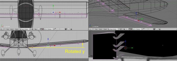
It is [x|, when tuning finely by Edit Mode and it leans by the dihedral angle.y|z] An aileron etc. will change into a parallelogram by edit of axial fixation.Then, a screen is rotated so that it may become level about an aileron, and [Orientation] is set to [Veiw] and edited.In Object Mode, Align View is used.([Shift]+[v] after choosing a field to make into a standard in Edit Mode)
-
An aileron is chosen.
-
[Object] [([Script] [Align View to Seleted]) ((XZ)) Front].However, since the 3rd page figure of a background does not rotate though regrettable, a sketch is not consulted.
-
Then, it edits lengthening an aileron by Edit Mode etc.
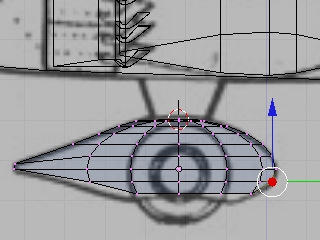
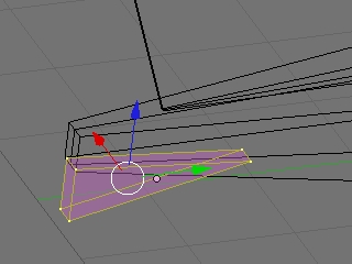
7) Creation of the spats of a main gear
Cube, UVsphere, Cylider, etc. are idea る as a basis figure.Here, a pole is created from Uvsphere carried out in the up-and-down direction.
-
It left-clicks by Object Mode and puts 3D cursor on the center of spats.[Add], [Mesh], and [UVsphere] -- [Segments:12], [Rings:12], and [OK]
-
[Pivot] -- [3D cursor], [s], and [g] -- [x|y|It unites with a front outside from an axle by z].
-
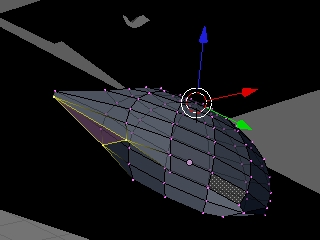
Edit Mode is used by [Tab] and the point of a left half is deleted by selection [x] [Verticese] by [a] and [b].Lower 3 step is deleted similarly.
-
Left-hand side is displayed by [Modifiers], [Add Modifier], and [Mirror].
-
A back point is chosen by [a] and [b], and it lengthens back by [s] and [y].An outline is united with a sketch, changing the point to choose.
-
The point of a back ridgeline is chosen and it unites with a sketch by [g] and [y] [x].
-
The point of the back bottom is chosen and it deletes by [x] [Vertices].
-
Two points of a lower square mesh are chosen, [Mesh], [Vertices], [Marge], [At First], and [Renoved 1 Vertices] are performed twice, and the bottom of back is made into a triangular mesh.The front bottom is also made into a triangular mesh only one piece.Shortcut is [Alt]+ [m].
-
[Tab], [Modifiers], [Mirror], [Apply], 3 - four-point selection [Mesh], [Faces], and [Make Edge/Face] are repeated, and a field is stuck on the bottom.
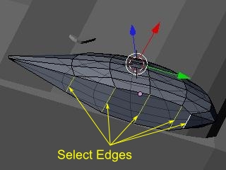
Since the spats of a main gear are completion now, the work after this is unnecessary.Here, the method of mirror-izing again so that it may be easy to correct later is introduced.
-
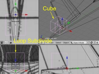
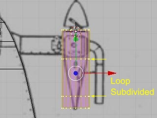
The created undersurface is divided into two.First, the neighborhood which is set to [Edit Mode] and [Edge select mode], and is divided into two by [Shift]+ right-click is all chosen.
-
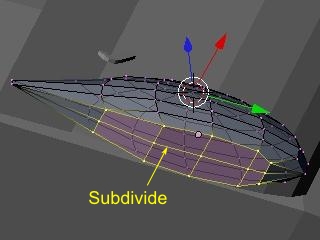
It divides into two by [w] and [Subdivide].
-
[Vertices select mode] is used and it is a left half at [a] and [b] Selection [x] [Vertices]
-
[Modifiers][Add Modifier][Mirror]
8) Spats creation of a front gear
A main gear is copied and created.
-
3D cursor is reset by [Object Mode] and [Shift]+ [c] centering on the body.
-
a right-click -- the spats of a main gear -- selection, [Object] and [Duplicate] (shortcut is [Shift]+ [d]), and [Enter]
-
[Shift]+ [s], [Selection -> Cursor]
-
マニュピレータ is dragged by left-click and it moves to the position of a sketch.
-
[Pivot] is set to [Median Center] and it is [s] [x|.y|An outside is united with a sketch by z].
9) Spats creation of a left-hand side main gear
Left-hand side spats are created by mirror-izing the spats of a right-hand side main gear on a body standard.
-
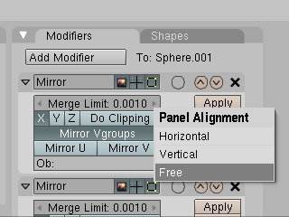
Right-hand side spats are chosen by [Object Mode], and "Cube" is inputted into [alumnus:] by [Modifiers], [Add Modifier], and [Mirror] [Enter].When [alumnus:] has overflowed the screen and "Cube" cannot be inputted, it right-clicks by lower [Buttons Window], [Free] is chosen, and it scrolls with a mouse wheel.▽ at the upper left of upper Mirror may be pushed, and the upper Mirror panel may be closed.
10) Creation of a tire
Although how to create a section to make with reality, make it rotate by Bezier Curve it, and make it into the shape of a doughnut can be considered, it makes from simple Cylider here.
-
[Add][Mesh][Cylinder][Vertices:16][Enter][OK]
-
Seemingly, Wheel of RealFlight will rotate correctly by turning an x-axis to body right-hand side.In Blender, the early x-axis is right-hand side.In order to maintain the direction of this axis, direction of Cylinder is changed by [Edit Mode].[Edit Mode] -- [r], [y], [90], and [Enter]
-
It returns to [Object Mode] and is [g] [s] [x|.y|It unites with the sketch of フロンド by z].
-
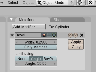
It cuts off the corners as [Width:0.5000] and [Angle] by [Modifiers], [Add Modifier], and [Bevel].
-
The x-axis y-axis of [Object] and [Duplicate] (shortcut is [Shift]+ [d]) [Enter] and マニュピレータ is dragged by left-click, and it moves to a right-hand side wheel position.
-
[s] Width of tire is united with a sketch by [x].
-
Name "Cube" of a body object is inputted into [alumnus:] by [Modifiers], [Add Modifier], and [Mirror], and it is [Enter].
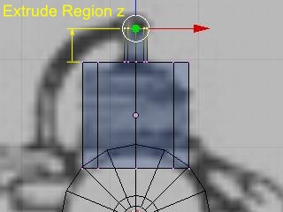
11) Creation of engine カウル
-
A mouse is left-clicked by [Object Mode] and 3D cursor is moved onto the central axis of right-hand side engine カウル.
-
[Add], [Mesh], [Cylinder], [Vertices:16], [OK], and [r] [x] [90], [Enter]
-
An outside diameter is united with a sketch by [s].
-
[Edit Mode] is used and a length direction is united by [a], [b], [g], and [y].
-
It is a loop cut by [Ctrl]+ [r], a left-click, and left-click.
-
Each section is united with a sketch by [a], [b], [s], and [Shift]+ [y], and it is scaling.
-
Name "Cube" of a body object is inputted into [alumnus:] by [Modifiers], [Add Modifier], and [Mirror], and it is [Enter].
12) Engine creation
-
[Object Mode][Add][Mesh][Cylinder][Vertices:8][OK]
-
An outside diameter is united with a sketch by [g] and [s].
-
The engine upper surface is chosen by [Edit Mode], [a], and [b].The [e] and [Region] left-click [s], [shift]+ [z], and a mouse are moved, and it reduces and left-clicks to the outside diameter of a plug.
-
A plug is extended by [e], [Region], and [z].
-
Name "Cube" of a body object is inputted into [alumnus:] by [Modifiers], [Add Modifier], and [Mirror], and it is [Enter].
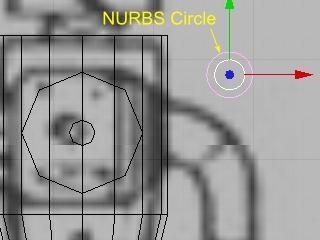
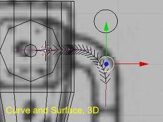
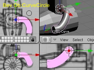
It creates by Bezier Curve.Refer to the following URL for the operation method of Bezier Curve.http://bigarrow.tea-nifty.com/blog/2012/01/blendercurve-80.html
In addition, not the method of the above-mentioned URL but the method to which other figures (NURBS Circle) are made to link is being used for the pipe in alignment with Bezier Curve.
-
[Object Mode][Add][Curve][NURBS Circle]
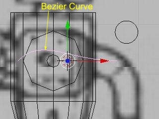
-
A mouse is left-clicked and 3D cursor is moved to the root of an exhaust pipe.
-
[Add][Curve][Bezier Curve]
-
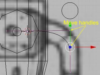
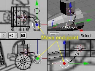
A corner point is arranged for the [Edit Mode] corner point to the termination of the curvilinear part of an exhaust pipe by right-click [g].
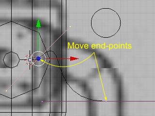
-
A handle is right-clicked, and it moves by [g], and prepares a form.
-
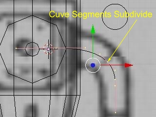
The corner point of both ends is chosen by the [Shift] right-click, and a control point is added in the middle by [Curve], [Segments], and [Subdevide].
-
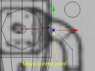
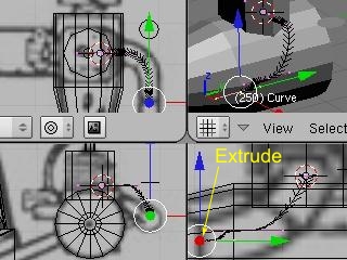
The added control point is chosen by right-click, and it moves by [g].
-
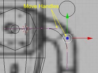
A handle is right-clicked, and it moves by [g], and prepares a form.
-
[Buttons Window][Curve and Surface][3D]
-
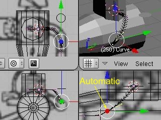
It lengthens to the muffler side by [e].
-
choosing the control point of the lengthened origin -- [Curve], [Control Points], and [Automatic] (shortcut is [Shift]+ [h])
-
Name "CurveCircle" of NURBS Circle created previously is put into [Buttons Window], [Curve and Surface], and [Bev Ob].
-
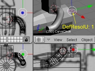
[Buttons Window], [Curve and Surface], and [DefResolU] are set to "3."
-
{Selection, [Buttons Window], [Curve and Surface], and [DefResolU] are set to "1" for Circle previously created by Object Mode].
-
Although Curve is changed into Mesh after this, since it becomes impossible to return to Curve, a file is saved just to make sure.
-
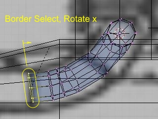
[Object Mode] -- an exhaust pipe -- selection, [Object], [Convert Object Type], and [Mesh] (shortcut is [Alt]+ [c])
-
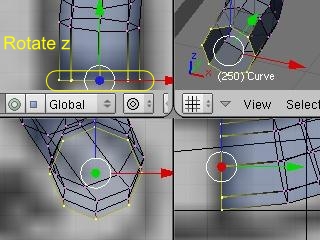
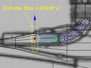
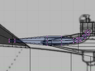
It is a point by the side of a muffler at [Edit Mode] and [b] Selection and [r] [x|Inclination is carried out to parallel by z] at a x-z plane.
-
It extends by [e], [Only Edges], and [y], and by a left-click and [s], scaling is carried out and it left-clicks.This is repeated.
-
Name "Cube" of a body object is inputted into [alumnus:] by [Modifiers], [Add Modifier], and [Mirror], and it is [Enter].
-
NURBS Curve previously created by [Object Mode] is chosen, and it is [x] [Erase selected Object (s)].
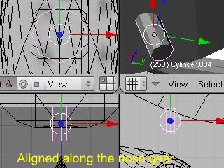
14) Creation of a nose leg
-
3D cursor is reset by [Object Mode] and [Shift]+ [c] centering on the body.
-
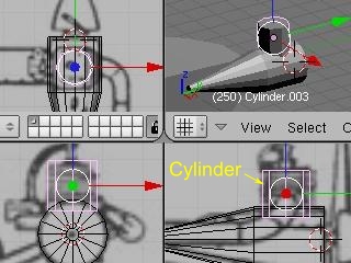
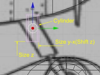
[Shift]+ [a] is pushed, [Add], [Mesh], and [Cylinder] are left-clicked, and they are [Vertices:8] and [OK].
-
[g][y|It moves to the position of a nose leg by z].
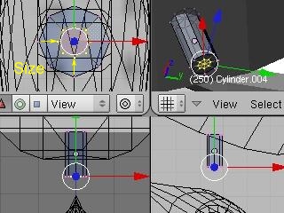
-
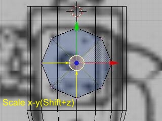
Width is approximately united by length and [s] [Shift]+ [z] by [Edit Mode], [s], and [z].
[Note] "Cylinder" must not perform scaling [s] by [Object Mode].If Scale is not "0", there are abnormalities which change a size by rotation by [Edit Mode].
-
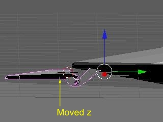
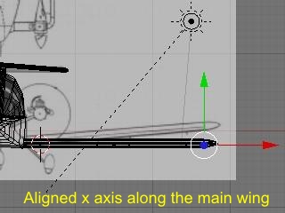
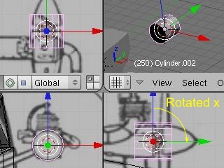
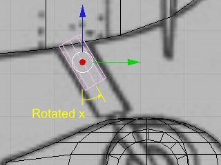
An angle is united with a sketch by [Object Mode] and [r] [x].
[Note] In order to rotate the axis of an origin together with an object, it is made to rotate by [Object Mode].
-
lower right Window -- [Object], [Scripts], [Align View to Selected (*1)], [Left (YZ)], [Orientation], and [View]
-
lower left Window -- [Object], [Scripts], [Align View to Selected (*1)], [Reat (ZX)], [Orientation], and [View]
-
upper left Window -- [Object], [Scripts], [Align View to Selected (*1)], [Top (XY)], [Orientation], and [View]
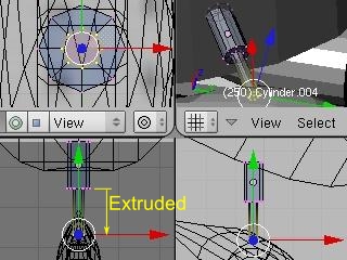
-
The bottom is reduced by [Edit Mode], [a], and [b], [e], [Region], [0], [Return], and the diameter of [s] are reduced by Window of selection and the upper left, and it left-clicks.It [Region] [ [e] and ] Extends by lower right Window, and is a left-click.
-
In the upper left Window, [1] is returned at [7] and the lower left Window, and View is returned by [3] at the lower right Window.
(*1): The function of "Align View" currently introduced with the tool useful for the modeling of the front one.When not having incorporated, [Shift]+[v] is used by [Edit Mode].
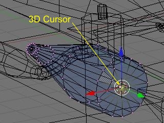
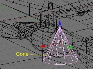
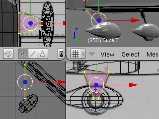
15) Creation of a spinner
-
Engine カウル is moved by [Object Mode] at the center of selection and the front of [Tab] engine カウル, and 3D cursor is moved by selection, [mesh], [snap], and [Cursor -> Selection].
-
[Tab][Add][Mesh][Cone][Vertices:8][OK]
-
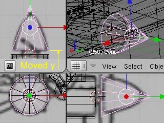
An outside is united with a sketch by [r] [x] [90], [-], [g], [y], and [s] [Shift]+ [y].
-
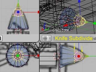
It is specification [Enter] by left-click about the corner point of the line segment cut by [Tab] and [a] by all the selection [Mesh], [Edges], and [Knife Subdivide] (shortcut is [Shift]+ [k]) [Midpoints].
-
An apical portion is chosen by [a] and [b], and it cuts with a knife once again.
-
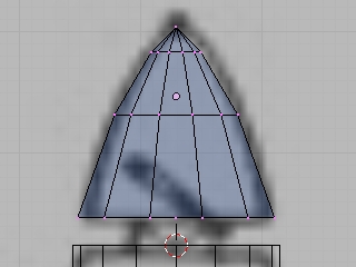
[a], [b], and [s] It unites with a sketch by [Shift]+ [y], [g], [y], etc.
-
Name "Cube" of a body object is inputted into [alumnus:] by [Modifiers], [Add Modifier], and [Mirror], and it is [Enter].
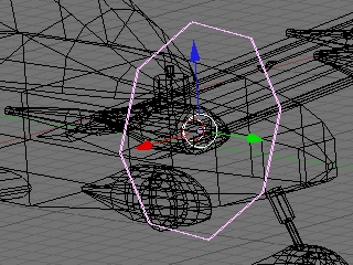
16) Creation of a propeller
Although the propeller created here is not displayed by RealFlight, the information on a display position and a rotation position is used.For this reason, it creates by the object which certainly has a field.
-
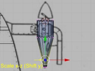
It is made thin by [Onjrct Mode], [Add], [Mesh], [Cylinder], [Vertices:8], [OK], and [r] [x] [90], [s], and [y], and an outside is expanded by [s] [SHift]+ [y].
-
Name "Cube" of a body object is inputted into [alumnus:] by [Modifiers], [Add Modifier], and [Mirror], and it is [Enter].
17) Creation of other objects
The leg of a main gear and an engine arm are created for an aileron, a nose leg, etc. to reference.尾そり is created from Cube.

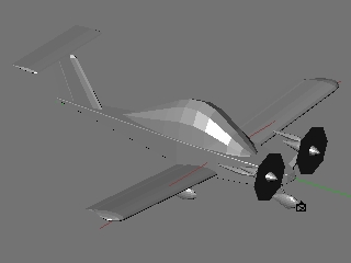
The solid form of 3D model is completion above.
18) For RealFlight 8 : Set the object's Scale to 1
In Blender's object mode, press [a] to select all objects and press [Ctrl + a] (Apply), [Scale] to set Scale to 1.
19) Supplementary information of modeling
It smooths (reference).
There are some which are ineffective at RealFlight.Even if it does not smooth by Blender, by the RealFlight side, there is also an object which becomes smooth freely and he cannot understand it.(For example, Sphere becomes smooth freely ?)
-
[Buttons Window][Link and Materials][Set Smooth]
It is [Set Solid] when canceling.
Invalid in RealFlight
-
Selection of [Buttons Window], [Mesh], and [Auto Smooth] will smooth less than the angle set up by [Degr:].It becomes effective at the time of the above [Set Smooth].3D An effect cannot be checked in Window.
Invalid in RealFlight
-
[Subsurf]
-
[Subdivide]
-
[EdgeSplit]
-
[Bevel]
Re-calculation of a normal line (reference)
Since the field which Smooth does not work well and is not displayed by a rendering will be made if direction of a normal line has not gathered, direction of a normal line is arranged.
-
The display of a normal line
[Edit Mode], [Editing] (F9), [Medh Tools], [Draw Normals], and [Draw VNormals] are turned ON.
-
The re-calculation of a normal line
Shortcut is [Ctrl]+ [N].
-
Reversal of a normal line
[Mesh Tools], [Flip Normal], or [W], [Specials], [Flip Normal]
Double problem (reference)
Since Smooth will not work well if the point is a ニ pile, it is unified.
-
[Mesh Tools], [Rem Doubles], or [W], [Specials], [Remove Doubles]
9. Name Change of Object
An object name and a material name with a specific function [*] were decided by RealFlight.The arbitrary names not overlapping are attached to オブジェク it is not decided that a name without a function in particular will be.Refer to the following URL for details.
http://www.knifeedge.com/KEmax/plane_tutorial.php (external link)
[*] The function which works on a simulator: A moving blade, a propeller, a wheel.The function which indicates by transparent on a simulator: A canopy, a translucent film, etc.
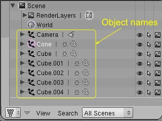
1) Window display change of Blender
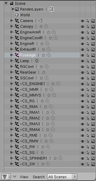
An object table is displayed, in order not to leak and to choose the object which changes a name.
-
Click the button at the lower left of upper right Window [Outiner].Window size is changed when an object name is not displayed (example: [Ctrl]+ [↑], [Ctrl]+ [↓]).
-
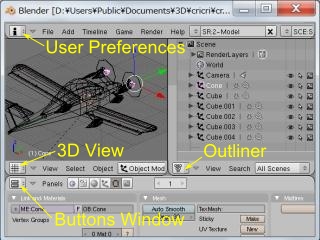
The boundary of the upper and lower sides Window is right-clicked, and [Join Areas] and lower Window are right-clicked.It carries out to Window of right and left [ this ], and they are [3D View] and Right Window about Left Window [Outliner].Lower Window is set to [Buttons Window] and a top is set to [User Preferences].
2) Change of an object name
-
The object which has not changed the name by [Outliner] is left-clicked.
-
The name of [Object Mode], [Buttons Window], [Editing] (F9), [Link and Materials], and [alumnus:] is changed into the name for RealFlight.
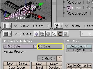
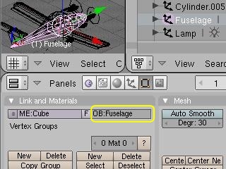
* : for the information on the following URL, the name of [ME:] instead of [alumnus:] is to be changed.However, it is more legible to change [alumnus:] at [Outliner].
http://www.knifeedge.com/KEmax/downloads/Blender2RealFlight.zip(external link)
* For the information on the following URL to which :export_3ds2kex.py is contributed, they are the directions which change the name of [alumnus:].It seems that this one is righter.In addition, export_3ds2kex.py of this page is old.A version high for next contribution is contributed.
Blender 3DS export project : http://www.knifeedge.com/forums/showthread.php?t=17674 (external link)
3) The name of cricri
Since it will get confused if an object name increases, although an object on either side is divided into the last with the application of a mirror modi fire, or the work which unifies an aileron hinge is required for an aileron, it names here.
A name with a function
-
Fuselage : body.Certainly required.It can fly, if it is this much.Although the body of FMS is one object, if Fuselage and a name are attached to this, it can be brought off to RealFlight.(A propeller does not rotate.)A moving blade does not move.
-
~CS_ENGINEn : n is 1, 2, and 3 ...Propeller.Since right and left are not separated at this time, it is referred to as n= 1.
-
~CS_MMR : Rudder.
-
~CS_MMVS : Vertical tail.
-
~CS_RG : The right main leg.
-
~CS_RMA : Right aileron.
-
~CS_RMAn : n is 1, 2, 3, and 4.The n-th hinge of a right aileron.However, since it unifies to a wing in this example later, any name is good.
-
~CS_RME : Right elevator.Although cricri is a premature start tail of one sheet, since this name is not defined by RealFlight, a right-hand side elevator is substituted for it.
-
~CS_RMW : Right wing.
-
~CS_RW : Wheel of the right main leg.
-
~CS_SG : Leg of a front wheel.
-
~CS_SPINNERn : n is 1, 2, and 3 ...Spinner.Since right and left are not separated at this time, it is referred to as n= 1.
-
~CS_SW : Front wheel.
A name without a function.Arbitrary names are attached by a half-width alphanumeric character.
-
Canopy : canopy.
-
EngineArmR : right engine arm.
-
EngineCowlR : right engine カウル.
-
EngineR : right engine.
-
ExhaustR : right exhaust pipe.
-
RGCowl : Cowl of a right main undercarriage wheel.
-
RearGear : -- a fish -- curving -- 。
-
SGCowl : Cowl of a front wheel.
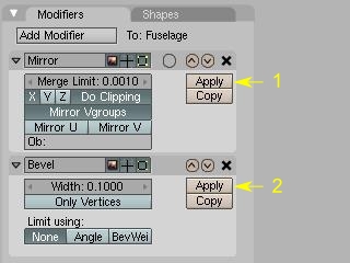
10. Application of Modi Fire
A modi fire may not be reflected in RealFlight.Then, it changes into Mesh data with the application of a modi fire (Apply).However, it is reflected in RealFlight even if it does not apply a modi fire to a mirror (Apply).
It is better for the mirror object which attaches the same texture as right and left to apply a mirror modi fire, after creating UV MAP explained later since only a right half should write a texture (Apply).
-
The object to which a modi fire is applied by [Object Mode] is chosen by right-click, and [Apply] of the [Modifiers] tab of [PanelsWindow] is left-clicked sequentially from a top.
returns next
2012/07/22 - 2012/02/19