This is how to make the photo scenery and landscape for FMS. Using tool are SimScene.exe and peff.exe which were made by Mr. Honda. SimScence.exe creates the photo scenery for FMS from cylindrical image panorama photo compounded by Hugin etc. I give a special thanks to Mr. Honda.
These tools are written by Japanese. Meaning of menu are here "explanation of menu".
Using version : SimScene Ver.1.81 and peff Ver.1.05 in Japanese (some pictures use an old version)
These soft can get from: 空雲礼賛 (http://fmskatsuhiko.web.fc2.com/ (external link))
Reference manual:
The way of obtaining an equidistant-cylindrical-projection (equirectangular) panorama picture are 1) downloading ready-made panoramic photograph, 2) taking a photograph and creating it by yourself. (Capter 4. and later on this page will be explained using downloaded data in the example of 1) below.)
1) How to download ready-made panoramic photographs
- (1) Download the example : Click [Flight Simulator] of the upper part of the homepage : "空雲礼賛" , and downloads the "岩見沢市陸上競技場(Iwamizawashi Higashiyamakouen rikujou kyougijou)" riku20110926.zip.
* Temporary link when you can not download : riku20110926.zip
- (2) Extract the downloaded zip file to an arbitrary folder. Example : C:\Program Files (x86)\FMS\Landscape\
Explanation of example files : "riku20110926.jpg" is an equidistant-cylindrical-projection (equirectangular) panorama picture, and "riku20110926_prv.jpg" is a preview screen of Landscape for FMS. (Since the preview picture is not usually attached to a panorama picture, it makes later.)
- Reference : Sites with panoramic images and photo scenary
-
2) How to take a photograph and create a panorama photograph by yourself
- (1) Refer to "how to make RealFlight G3.5 and the photograph field for FMS alpha 8.5" etc.
- (2) Copy the created panorama picture to a suitable folder. Example : C:\Program Files (x86)\FMS\Landscape\
- Reference : Making information sites
-
3) How to use images from other simulators
RealFlight and Phoenix R/C and other photo fields with 6 faces cubic images can be used. In this case, since it has already been divided into six faces, the work of SimScene.exe in chapter 4 is unnecessary. Below is an example of using PhotoField for RealFlight G3.5.
- (1) Get Photo Field for RealFlight
- Open the following URL and follow [Forums] - [Swap Pages] - [RealFlight G3.5] - [Airports] - [Custom PhotoFields] and download your favorite photo field.
- - Knife edge : http://www.knifeedge.com/
- (2) Get 6 faces images
- If the extension of the downloaded file is .g3x, rename it to .zip and expand it.
- (3) Change file format
- Read the .dds file in Paint.NET or other software to read the DirectDraw Surface (DDS) format, and save it in .bmp format. Do not include spaces in file names. It is good to set the image size to 1024 x 1024 pixels.
- - Paint.NET : http://www.getpaint.net/
-
- [base name]_1.dds -> [base name]_front.bmp
- [base name]_2.dds -> [base name]_right.bmp
- [base name]_3.dds -> [base name]_back.bmp
- [base name]_4.dds -> [base name]_left.bmp
- [base name]_5.dds -> [base name]_top.bmp
- [base name]_6.dds -> [base name]_bottom.bmp
- Reference : If imported into RealFlight G3.5, there is a .dds file in C:\Program Files\RealFlightG3\Airports\PhotoFields\Aerodrome Name\.
- * Since the image file can not be extracted from Phoenix R/C's site distribution file .pkg, they are picked up the one that are installed into Phoenix R/C.
- The .dds file (4096x4096) installed to Phoenix R/C 5.5 is in C:\User\[User name]\Documents\PhoenixRC\Downloaded\Sites\User-made\[Site name]\high\.
- (4) Create a scene file
- a. Click [File]-[Open 6face image] in the peff menu and read one .bmp file. (If you specify one, the remaining five are automatically loaded.)
- b. Confirm that the image is displayed and the parameters are as follows.
- Size : 1000, Angle : 0.00, Aircraft : X=-5, Y(FMS z)=-1.7, Z(FMS y)=0, Update : checked
- c. Click [File] - [Save As], save the name as "[base name].scn".
- So far, [base name].scn, [base name].pfo, fms_vista.bmp (if no existing) will be created.
- (5) Proceed to the next step
- So far, 6 faces images, scene file ([base name].scn), [base name].pfo, fms_vista.bmp (if no existing) has been created. Therefore, the task of Chapter 4 is unnecessary. However, since there is no polygon (= there is no ground), please proceed to chapter 5 or chapter 6 and create at least ground.
The airfield graphics file (6 facescubic) and .scn file for FMS are created from an equidistant-cylindrical-projection (equirectangular) panorama picture.
- 1) Execute SimScene.exe. Example: [Start]-[all program]-[Flying Model Simulator]-[SimScene]
- 2) Click the button [...] on the right side of the graphics file name in a project tab, and select an equidistant-cylindrical-projection (equirectangular) panorama picture. Example : C:\Program Files (x86)\FMS\Landscape\riku20110926.jpg
- 3) Enter the scene file name with the full path, or click the right button [...] to select it. Example: C:\Program Files(x86)\FMS\Landscape\riku20110926.scn
(Since there is no scene file at the beginning, entering the path name is easier if you select another scene file and rewrite the file name.)
- 4) Put the base name of an output picture (6 faces cubic) for FMS. Example : riku20110926 * Do not include spaces in the base name.
- 5) Set up as follows, Scene type = a cube (6 faces), Suffix name = _left .. _Bottom, Output picture size = 1024, Output picture type = Bitmap. Check the output a division graphics file. Check the output a scene file.
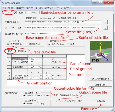
- 6) Click [Execute output] button on the right-low and waits for a while.
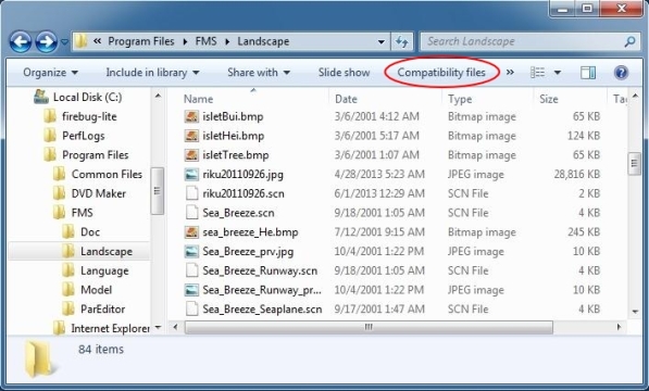
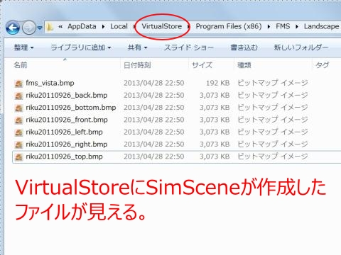
- 7) To make sure that the following file has been created in the Explorer. If there is no file in "C:\Program Files(x86)\FMS\Landscape\", see "C:\Users\[login user name]\AppData\Local\VirtualStore\Program Files(x86)\FMS\Landscape\". In case of Windows 7, open "C:\Program Files(x86)\FMS\Landscape\ in Explorer and click "Compatibility File" to display "C:\Users\[login user name]\AppData\Local\VirtualStore\Program Files(x86)\FMS\Landscape\".
-
- Scene file : riku20110926.scn
- Dummy picture for Vista or later : fms_vista.bmp
- Back picture : riku20110926_back.bmp
- Lower picture : riku20110926_bottom.bmp
- Front picture : riku20110926_front.bmp
- Left picture : riku20110926_left.bmp
- Right picture : riku20110926_right.bmp
- Upper picture : riku20110926_top.bmp
- * Tips : For Phoenix R/C site
- You can create an airport for Phoenix R/C by capturing the 6 faces square image (4096x4096) generated by SimScene.exe with PhoenixBuilder.
The correspondence between image file name and Panels of PhoenixBuilder's Panoramas Cube Pano Properties is as follows. +X=front/1、+Z=right/2、-X=back/3、-Z=left/4、+Y=top/5、-Y=bottom/6
For details, please refer to the following site. : http://www.phoenix-sim.com/guides.asp
http://www.phoenix-sim.com/guides/PhoenixGuides_creator.pdf
There is a detailed guide in the following folder. : C:\Program Files (x86)\PhoenixBuilder\resources\userGuide\userGuide.rtf
- 8) How to make a preview file
-
- (1) Copy an above picture file which you want to use as preview file to desktop, rename it [file name in front of "." of .scn]_prv.jpg. Example: riku20110926_prv.jpg
- (2) Open the file by Paint. Click [Resize and skew]-[pixel] in image of ribbon, set Horizontal and Vertical value to 200 pixels, click [OK].
- (3) Move a preview file to the same folder as a scene file. Example: C:\Program Files (x86)\FMS\Landscape\
- 9) Delete the original panorama picture, if you don't need it. Example: riku20110926.jpg
- 10) Execute FMS, click [Landscape]-[Load...], select .scn file. Example: riku20110926.scn
Photo scenery which has flat surface of the earth is loaded into FMS and you can use it. This is enough if it uses for R/C flight operation practice.
Make a sketch which is a guide for the placement of polygons from a satellite photograph, a map, a plan view, and the like. The sketch is not essential, but it is convenient to have it.
1) Confirm center position and direction of panoramic image
Open the scene file (.scn) with FMS and check the direction of the front and the position of the foot (origin). If you have not created a scene file with SimScene.exe, open the scene file with peff.exe, click [Wiew]-[Origin] and check the direction of the front and the position of the foot (origin).
2) Creating sketch
- (1) Display a satellite picture or a map so that the shooting position of the panorama is the center with Google Earth or a map software. (For Google Earth, use [View] - [Reset] - [Slope] to make the picture from directly above.) (You can adjust the deviation later, but keep it as accurate as possible because later correction work will be easier.)
-
- (2) Display scale showing distance on the satellite photos or map. (For Google Earth, [View] - [Scale Legend])
- (3) Adjust the display scale so that the range where you want to place the object (polygon) is displayed.
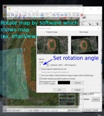
- (4) Rotate the satellite picture or map so that the front direction is to the left.
- (5) Save the image to the file for the sketch. (In the case of Google Earth, you can copy the image to the clipboard with [Edit] - [Copy image], make the image of the clipboard into a file with IrfanView, etc. You can copy the screen with the [Print Screen] key.)
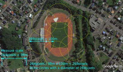
3) Add reference circles
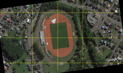
Open the sketch with image editing software such as Inkscape or GIMP, measure the length of the scale in pixels, and calculate the number of pixels of 100 m. Then, write a plurality of circles having a diameter of the number of pixels corresponding to 100 m on the sketch and save the sketch.
4) The creation of the ground and grid
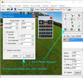
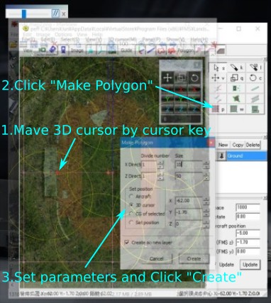
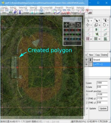
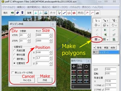
- (1) Open the scene file (.scn) [*] with peff.exe and click the [Create Polygon] button to create a polygon that becomes a grid with 100 m intervals on the ground with the following settings.
Number of divisions: X = 10, Y = 10. Size: X = 1000, Y = 1000. Set position: Set position, X = 0, Y = height of the ground when the height of the shooting camera is 0 m (eg -1.7 m), Z = 0.
* : If you save the scene file to "C:\Program Files(x86)\FMS\Landscape" with SimScene.exe but there is no scene file there, you can find it in "C:\Users\[Login user name]\AppData\Local\VirtualStore\Program Files(x86)\FMS\Landscape", so open it.
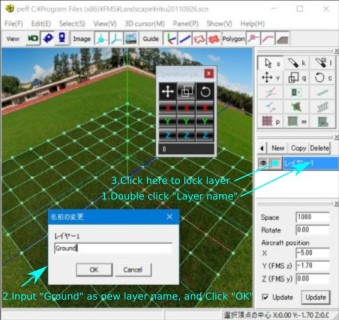
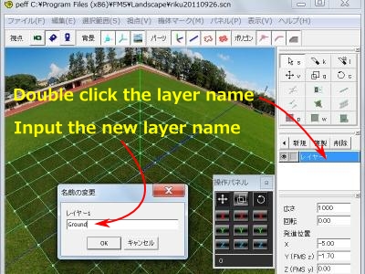
- (2) Double-click the layer name and set its name to "Ground". Then, attach a key mark to the layer so that it can not be edited.
5) Match the scale of the sketch and peff
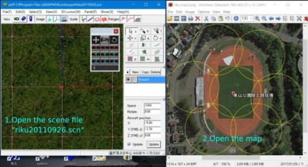
- (1) Click [View]-[Origin] with peff and move the viewpoint to the origin, click on [View]-[Top] to display from the top of the origin.
- (2) Display the sketch with software that can display images such as IrfanView by rotation or scaling.
- IrfanView : http://www.irfanview.com/
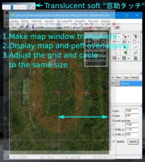
- (3) Run "窓助タッチ(winthrutouch.exe)" to transparently display the window, and make the window displaying the sketch a translucent display. Then, click the "//" button (toggle) of "窓助タッチ(winthrutouch.exe)" so that the window on the back side can be operated. (Substitute wintrutouch.exe for functions like blender's background image.
- 窓助タッチ(winthrutouch.exe) : http://www.geocities.co.jp/SiliconValley-SantaClara/1613/soft.html
- (4) Change the display scale of peff by changing the window size of the mouse wheel and peff so that the grid of the Ground polygon (100 m) and the circle of the sketch (100 m) are the same size.
6) Coarse adjustment of sketch and peff position (x position, z position)
Move both window positions so that the origin of peff comes to the position of the foot (origin) of the sketch.
7) Creating polygons for alignment
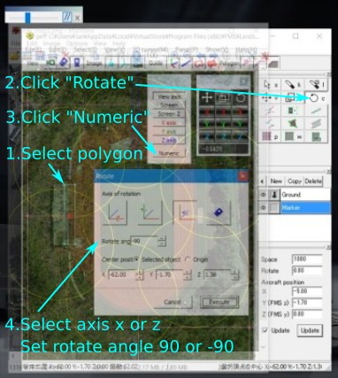
Decide three or more objects[*2] whose direction looks accurate near the camera's height[*1] , create reference polygons with a vertical edge at that position on a layer separate from Ground. Specifically, create a horizontal rectangular polygon and rotate it 90 degrees around the x or z axis to make it vertical. Make the layer name "Marker". Then, select all the polygons of the "Marker" layer.
*1:The height is exactly the height of the horizontal plane at the center of the equirectangular panoramic image. Usually it is the face of the camera's pan so it will be the height of the camera.
*2:Select the objects so as not to bias the same kind of orientation. In this example, we chose the gates of the grand, the center house, the steps on the other side of the center.
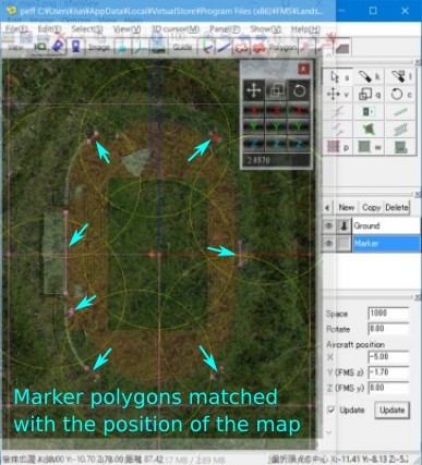
8) Adjustment of reference polygon position (x position, z position, y rotation)
- (1) Click [View]-[Origin] with peff, drag the mouse with the right click and check the horizontal deviation of the reference polygon and the panoramic background picture.
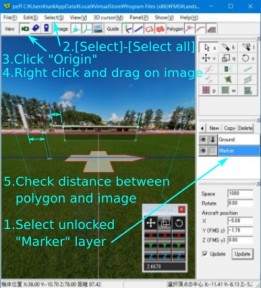
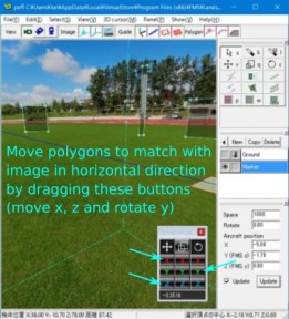
- (2) Align the reference polygons with the background only by moving in the horizontal direction of the X and Z axes and rotation about the Y axis. At this time, you should do it in the following procedure.
-
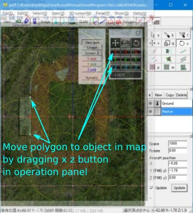
- a. The reference polygons are moved in the X and Z axis directions so that the horizontal deviation amounts of all the polygons are the same distance.
- b. Rotate the reference polygons around the Y axis to make the reference polygons and the background coincide.
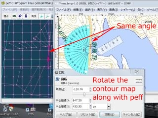
9) Rotation of sketch (y rotation)
- (1) Click [View]-[Origin] with peff and move the viewpoint to the origin, click on [View]-[Top] to display from the top of the origin.
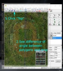
- (2) Rotate the sketch so that the position of the reference polygons and the position of the sketch coincide. (In the case of IrfanView, rotate by [Image]-[Custom/Fine rotation] and save it.In case of Inkscape, rotate by [object]-[transformation]-[rotation].)
- 分度器で測りましょ : http://www.vector.co.jp/soft/winnt/util/se345469.html
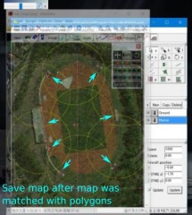
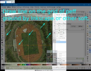
- (3) Add grid lines to the sketch with GIMP, Inkscape or the like so as to overlap the grid of peff's Ground polygon and save it.
In the above process, since the x and z coordinates and the rotation angle of the y axis of the sketch and peff coincide. (Then creates polygons in accordance with the sketch (described later). When finished, delete the alignment polygon at the end.)
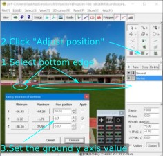
10) Misalignment of the ground plane in the height direction (z position, x rotation, z rotation)
In this example, the ground plane polygon and the actual ground plane are the same plane shape. So, with the viewpoint of peff as the origin, by changing the coordinates of the z axis and rotating the x and z axes, it is possible to match the ground height of the ground polygon with the height of the ground of the panoramic photograph.
The procedure is as follows.
- (1) Set the z coordinate value of the side (lower side) that is in contact with the ground of the previously prepared reference polygons to the ground height (eg -1.7(m)).
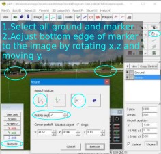
- (2) Remove the key mark of the Ground layer and select all the polygons of the Ground layer and the Marker layer.
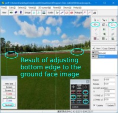
- (3) The differences between the height of the lower side of the background and the reference polygons with the viewpoint as the origin are matched by the movement of the polygon in the z axis direction and the rotation of the center of the x and z axes.
- (4) Set the height of the airplane slightly higher than the height of the ground.
Geographical feature and an obstacle are written in .scn.
1) Reading of a scene file
- (1) Execute peff.exe. Example: [Start]-[all program]-[Flying Model Simulator]-[peff]
- (2) Click [File]-[Open], select .scn file. Example: riku20110926.scn
2) Create the flat plane ground used as a runway.
If you have not created a ground for runway surface in the previous chapter, first make a polygon which is a simple horizontal plane. Size is 1000 m square and it is divided into ten at 100-m interval for an example.
- (1) Click [polygon p] button in a right tool box.
- (2) Set X and Z of [Division] to 10. Set X and Z of [Size] to 1000 m. Set [Set posision] to [Set numerical], and set X and Z to 0 m, and set Y to the distance from a shooting photograph position to the level of runway surface (usually minus value of shooting photography height), in an example, set Y to -1.7 m and click [Execute].
- (3) Double-click a layer name "レイヤー1" in the right layer panel, and change name to "Ground".
3) Create the center house.
Measure the position and size of the center house by Google Earth, and make the polygon of the center house by peff. If you are creating a sketch in the previous chapter, click [View]-[Origin] with peff and move the viewpoint to the origin, click on [View]-[Top] to display from the top of the origin, then move to (5) after making the underlay a translucent display and aligning the position and scale of peff.
- (1) Display a photography place by Google Earth. Example : Search "岩見沢市役所 東山公園陸上競技場(Iwamizawa city higashiyama park athletic field)" with Google Earth.
(If there is no artifact and there is large drop of terrain, it is good to use a map software such as Kashimir 3D (http://www.kashmir3d.com/(external link)) which can display contour line instead of Google Earth.)
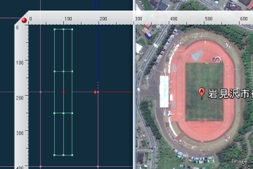
- (2) Click [Origin] button in [Viewpoint] section of peff tool bar, a viewpoint is moved to the origin. Click [Top view] button in [Viewpoint] section. Align both peff and Google Earth window. Ajust direction of Google Earth as peff. Click [Display]-[reset]-[inclination] in Google Earth to display top view.
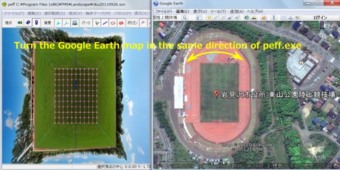
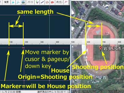
- (3) Measure the length of 100 m on the screen by the scale at lower left of Google Earth. Ajust zoom magnification of peff by rotating mouse wheel and changing window size so that both grid length of the runway polygon created previously and the length of 100 m on the screen in Google Earth become same length.
(Tips : It is useful for measuring length on screen to use Window Ruler (http://www.hexagora.com/en_dw_winruler.asp (external link)) or 測ルンです (http://onegland.main.jp/hakarun/(external link)).測ルンです can change scale to read length per metre directly.
- (4) When peff and Google Earth have same direction and scale, activate Google Earth, capture screen by [Alt]+[Prt Sc]. Paste it into a graphics editing software such as IrfanView (http://www.irfanview.com/(external link)), and save it as an image file for sketch.
- (5) Display the sketch on screen by すけふれーむ (http://s-mart.rgr.jp/gc/sukegazo/(external link)), and overlay the sketch on peff window.
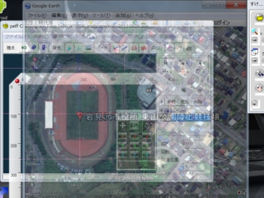
- (6) Move a 3D cursor of peff to position of the center house by cursor key. (3D cursor : It is a pointer which can specify a position where a polygon will be created like 3D Cursor of blender.)
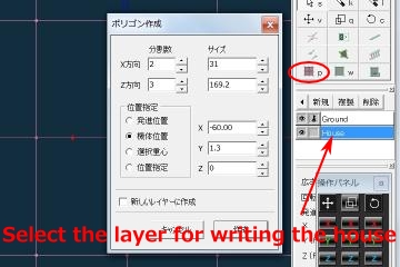
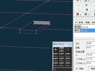
- (7) Click [New] button in the layer panel, double-click an added layer name, change an added name to "House". Attach a key mark of each layer except "House" layer, and click "House" layer to select.
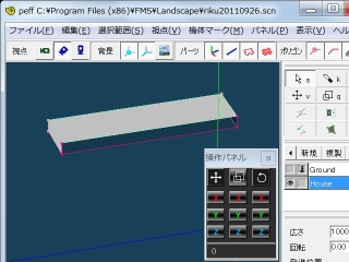
- (8) Click [Make polygon p] button of a right tool panel. Set X of [Division] to 2, Z of [Division] to 3. Set X of [Size] to 31 m (2 times a depth of 15.5 m of center house), set Z of [Size] to 169.2 m (3 times a width of center house), set Y of [Size] to 1.3m (Center house height 3m + runway height -1.7 m), and click [Execute]. (The depth and width of a center house are read in Google Earth. Since height will be corrected later after, it may be rough value.)
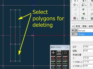
- (9) Click [Select s] button of the tool panel on the right of peff, and choose and delete the face of upper right and lower right of the polygon of the center house. The 3 faces of up down right will become a wall.
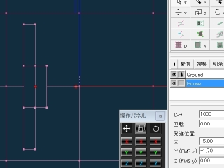
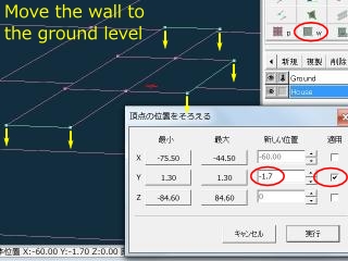
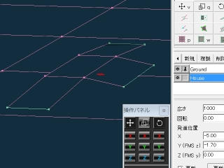
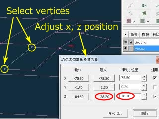
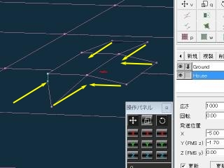
- (10) Select all vertices below the wall, click [Fit w] button, and set Y to -1.7. Then, select 1 pair of vertices of the upper and lower sides of a left wall, and set x and z to the upper position by [Fit w]. If the left wall is stood, select the vertex under this side of the left wall and the vertex at the lower left of a front wall in order, and click [Join at 1st] button.
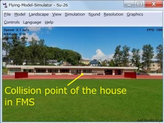
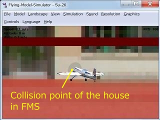
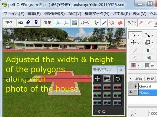
- (11) Click [Viewpoint]-[Origin] and [Back image], and check the position gap between the polygon and photograph of center house.
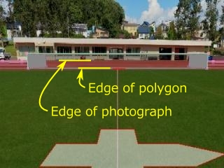
Thus, when the position of the bottom of a building has shifted from photograph, either depth direction (x) or the height direction (y) is wrong. Considering the gap with the width of the house of a polygon, and the center house of the lattice of the polygon of a bottom surface, the bottom surface and the house may be located in a higher position (y) (= shootong photograph height is low), and photography position (x) may be closer to the house. Then, when the bottom surface and the position of the photograph were checked, it turned out that inclination of the bottom surface and the photograph is not in alignment.
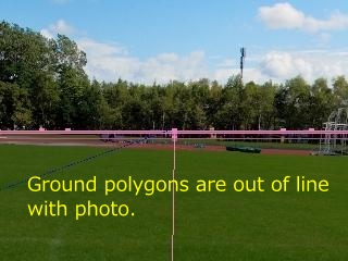
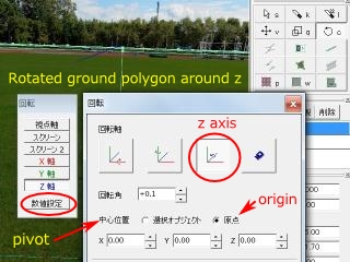
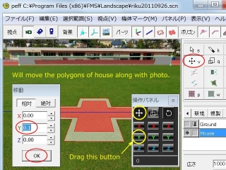
- (12) When the photograph leans, it recompounds by hugin using the photograph before composition. When the bottom surface leans, select all bottom surface by peff and it leans according to a photograph. Specifically, click [Select]-[Deselect all], and clear a key mark of "Ground" layer only, click [select]-[Select all] for selecting all bottom surface, click [Rotate c] in the right tool panel, click [Set numerical], change the X-axis or the Z-axis little by little (for example, 0.1 degrees), and adjust inclination of the polygon with a photograph.
Click [File]-[Save] by peff, run an airplane by FMS, and adjust the position of the house poligon by peff.
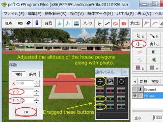
- (13) If the position of the center house of depth direction (x) is decided, next move the height (y) of the whole center house so that the lower side of a front wall will be united with a photograph. Then, move only z axis of the wall on each side, move y axis of the upper surface of house, so that it unites with a photograph.
- (14) Slelect a front face of the center house and click [Select]-[Add texture T]. Now, if the aircraft goes behind the center house, the aircraft will disappear in FMS.
- (15) Since the back faces of house are showed from viewpoint except the front face of house, select the faces of house except front one, click [Select]-[Flip polygon normal] for reversing. It prevents a red line coming out at a polygon edge. Then, a center house is completed.
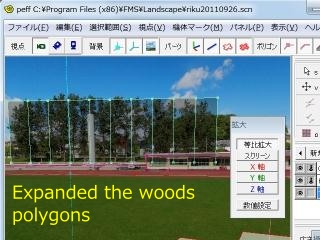
4) Create the woods at the left rear of the center house.
Create a perpendicular plane polygon and display the woods on it as texture.
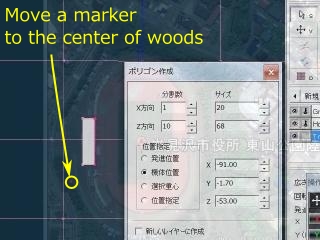
- (1) Move a 3D cursor to the front middle position of the woods by a cursor key.
- (2) Attach a key mark to the all existing layer, click [New] button in the layer panel, double-click a created layer name, and rename to "Tree_7" , and it is made a selective state.
- (3) Click [Make polygon p] button of a right tool panel. Set X of size to 68 m, Y of size to 20 m. Set X of division to 10, Z of division to 1. (The value width is read from Google Earth. Height is rough value.)
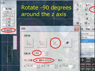
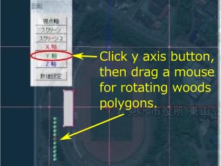
- (4) Click [Rotate c]-[Set numerical]-[Z-axis], set angle to -90, click [Execute], so that the polygon is stood perpendicularly.
- (5) Click [Rotate c]-[Y axis], drag a left button of mouse so that the angle of a polygon is fitted to the sketch.
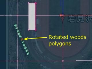
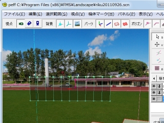
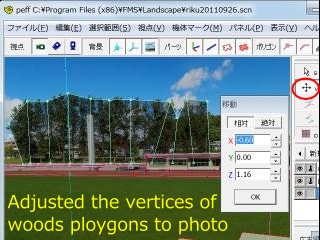
- (6) Click [View point (V)]-[Origin], drag a left button of mouse so that the woods shows center. (In this example, the polygon of woods does not match with photograph. It seems to be caused by a gap between origin of sketch and panorama image. But this is no ploblem bcause the woods is far from view point.)
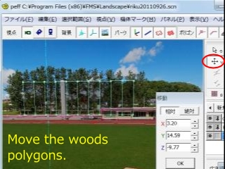
- (7) Click [Move v], and drag a left button of mouse to fit the position of polygon to the woods of photograph.
- (8) Click [Resize], and drag a left button of mouse to fit the position pf polygon to the woods of photograph.
- (9) Select each vertices, click [Move v], and drag a left button of mouse to fit the position of polygon to the woods of photograph.
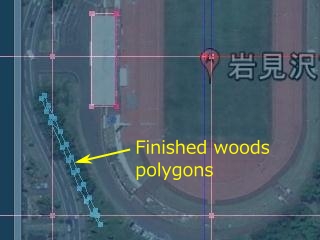
- (10) Select all polygon of woods, click [Select]-[Add texture(T)]. If a aircraft goes behind the woods, the aircrft will disappear.
The made files (riku20110926.scn、riku20110926.pfo) so far are in riku20110926scn.zip . If you think that works of chapter 5. and 6. are annoying, unpack this file, input them into folder witch was made in chapter 4. after works of chapter 4., and open riku201109260.scn from peff.exe.
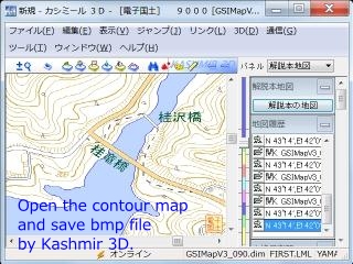
The proposal using the map which has a contour line in a sketch. It seems that fitting with a map will become easy if a photograph is horizontally taken with the level and a camera position (x, y, z) and a photography direction are known ?
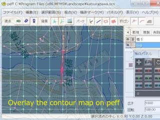
- 1) Display the map with the map software "Kashmir 3D", and prepare a drawing in the sketch of "5. Creating a sketch" above.
- 2) Display a sketch with 'すけふれーむ' or 'IrfanView' + '窓助タッチ(winthrutouch.exe)' etc., superimpose it on peff and change the display magnification and window size of peff so that it becomes the same scale.
- 3) Make a polygon according to the contour line.
Idle talk: I found a software (shareware) which can make 3D data from a map called 3DWear Landscape . It can output STL file, read STL file by blender and save x file...?
SimScene.exe and peff.exe are for Japanese windows. To display Japanese menu in English windows 7 Ultimate or Enterprise,[Start]-[Control Panel]-[Clock, Language, and Region]-[Region and Language]-[Administrative]-"Language for non-Unicode programs" -- []-[Japanese [ Change system locale. .. ]] (Japan)-[OK]-[Restart now] ... Restart
Translation of menu in English